
Full resolution (JPEG) - On this page / på denna sida - 1958, H. 4 - An Insulated Cable for Heavy Power Transmission, by Bror Hansson
<< prev. page << föreg. sida << >> nästa sida >> next page >>
Below is the raw OCR text
from the above scanned image.
Do you see an error? Proofread the page now!
Här nedan syns maskintolkade texten från faksimilbilden ovan.
Ser du något fel? Korrekturläs sidan nu!
This page has never been proofread. / Denna sida har aldrig korrekturlästs.
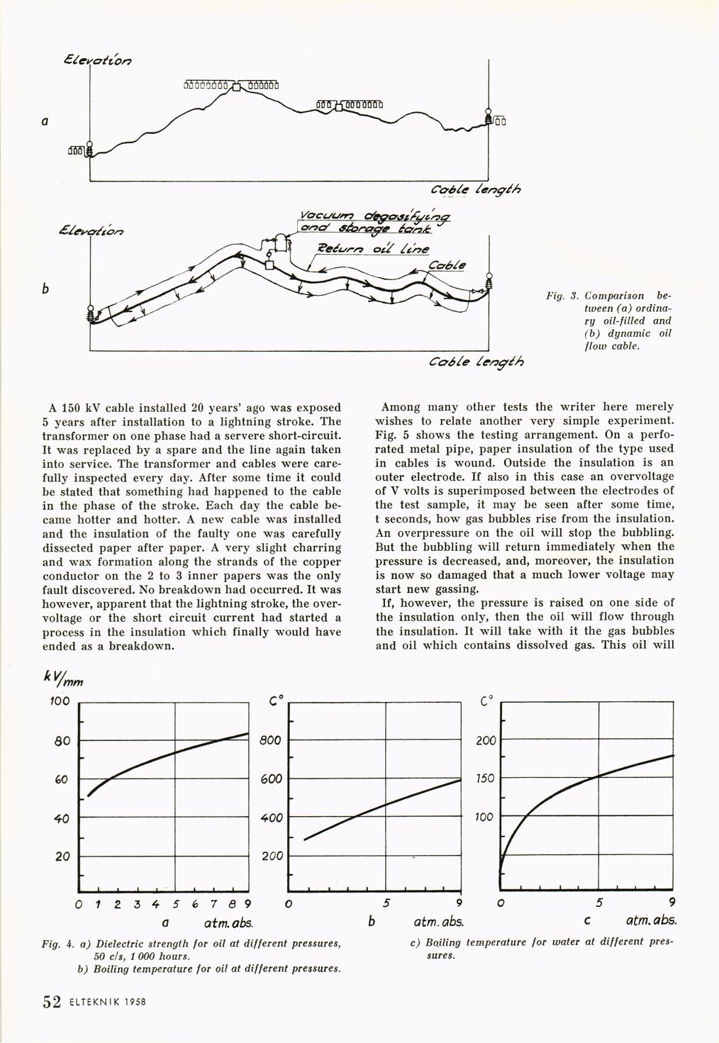
Fig. 3. Comparison
between (a)
ordinary oil-filled and
(b) dynamic oil
flow cable.
A 150 kV cable installed 20 years’ ago was exposed
5 years after installation to a lightning stroke. The
transformer on one phase had a servere short-circuit.
It was replaced by a spare and the line again taken
into service. The transformer and cables were
carefully inspected every day. After some time it could
be stated that something had happened to the cable
in the phase of the stroke. Each day the cable
became hotter and hotter. A new cable was installed
and the insulation of the faulty one was carefully
dissected paper after paper. A very slight charring
and wax formation along the strands of the copper
conductor on the 2 to 3 inner papers was the only
fault discovered. No breakdown had occurred. It was
however, apparent that the lightning stroke, the
over-voltage or the short circuit current had started a
process in the insulation which finally would have
ended as a breakdown.
Among many other tests the writer here merely
wishes to relate another very simple experiment.
Fig. 5 shows the testing arrangement. On a
perforated metal pipe, paper insulation of the type used
in cables is wound. Outside the insulation is an
outer electrode. If also in this case an overvoltage
of V volts is superimposed between the electrodes of
the test sample, it may be seen after some time,
t seconds, how gas bubbles rise from the insulation.
An overpressure on the oil will stop the bubbling.
But the bubbling will return immediately when the
pressure is decreased, and, moreover, the insulation
is now so damaged that a much lower voltage may
start new gassing.
If, however, the pressure is raised on one side of
the insulation only, then the oil will flow through
the insulation. It will take with it the gas bubbles
and oil which contains dissolved gas. This oil will
Fig. 4. a) Dielectric strength for oil at different pressures,
50 c/s, 1 000 hours,
b) Boiling temperature for oil at different pressures.
ELTEKNIK 1958 1 52
c) Boiling temperature for water at different
pressures.
<< prev. page << föreg. sida << >> nästa sida >> next page >>