
Full resolution (JPEG) - On this page / på denna sida - 1958, H. 4 - An Insulated Cable for Heavy Power Transmission, by Bror Hansson
<< prev. page << föreg. sida << >> nästa sida >> next page >>
Below is the raw OCR text
from the above scanned image.
Do you see an error? Proofread the page now!
Här nedan syns maskintolkade texten från faksimilbilden ovan.
Ser du något fel? Korrekturläs sidan nu!
This page has never been proofread. / Denna sida har aldrig korrekturlästs.
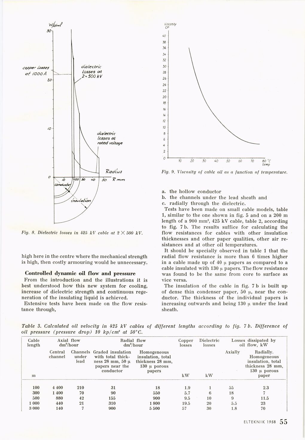
Fig. 8. Dielectric losses in 425 kV cable at 2 X 500 kV.
high here in the centre where the mechanical strength
is high, then costly armouring would be unnecessary.
Controlled dynamic oil flow and pressure
From the introduction and the illustrations it is
best understood how this new system for cooling,
increase of dielectric strength and continuous
regeneration of the insulating liquid is achieved.
Extensive tests have been made on the flow
resistance through,
Fig. 9. Viscosity of cable oil as a function of temperature.
a. the hollow conductor
b. the channels under the lead sheath and
c. radially through the dielectric.
Tests have been made on small cable models, table
1, similar to the one shown in fig. 5 and on a 200 m
length of a 900 mm2, 425 kV cable, table 2, according
to fig. 7 b. The results suffice for calculating the
flow resistances for cables with other insulation
thicknesses and other paper qualities, other air
resistances and at other oil temperatures.
It should be specially observed in table 1 that the
radial flow resistance is more than 6 times higher
in a cable made up of 40 |.i papers as compared to a
cable insulated with 130 u papers. The flow resistance
was found to be the same from core to surface as
vice versa.
The insulation of the cable in fig. 7 b is built up
of dense thin condenser paper, 50 u, near the
conductor. The thickness of the individual papers is
increasing outwards and being 130 j.i under the lead
sheath.
Table 3. Calculated oil velocity in 425 kV cables of different lengths according to fig. 7 b. Difference of
oil pressure (pressure drop) 10 kp/cm’ at 50°C.
Cable length Axial flow dm3/hour Radial flow dm3/hour Copper losses Dielectric losses Losses dissipated by oil flow, kW
m Central channel Channels under lead Graded insulation with total
thickness 28 mm, 50 ^ papers near the conductor Homogeneous insulation, total thickness 28 mm, 130 [x porous papers kW kW Axially Radially. Homogeneous insulation, total thickness 28 mm, 130 [.i porous paper
100 4 400 210 31 18 1.9 1 55 2.3
300 1 400 70 90 550 5.7 6 18 7
500 880 42 155 900 9.5 10 9 11.5
1 000 440 21 310 1 800 19.5 20 5.5 23
3 000 140 7 900 5 500 57 30 1.8 70
ELTEKNIK 1958 1 55
<< prev. page << föreg. sida << >> nästa sida >> next page >>