
Full resolution (JPEG) - On this page / på denna sida - 1958, H. 6 - Up-to-date Criteria in the Construction of Equipment for High Voltage Power Systems According to the Experience of the 400 kV System in Sweden, by Gunnar Jancke
<< prev. page << föreg. sida << >> nästa sida >> next page >>
Below is the raw OCR text
from the above scanned image.
Do you see an error? Proofread the page now!
Här nedan syns maskintolkade texten från faksimilbilden ovan.
Ser du något fel? Korrekturläs sidan nu!
This page has never been proofread. / Denna sida har aldrig korrekturlästs.
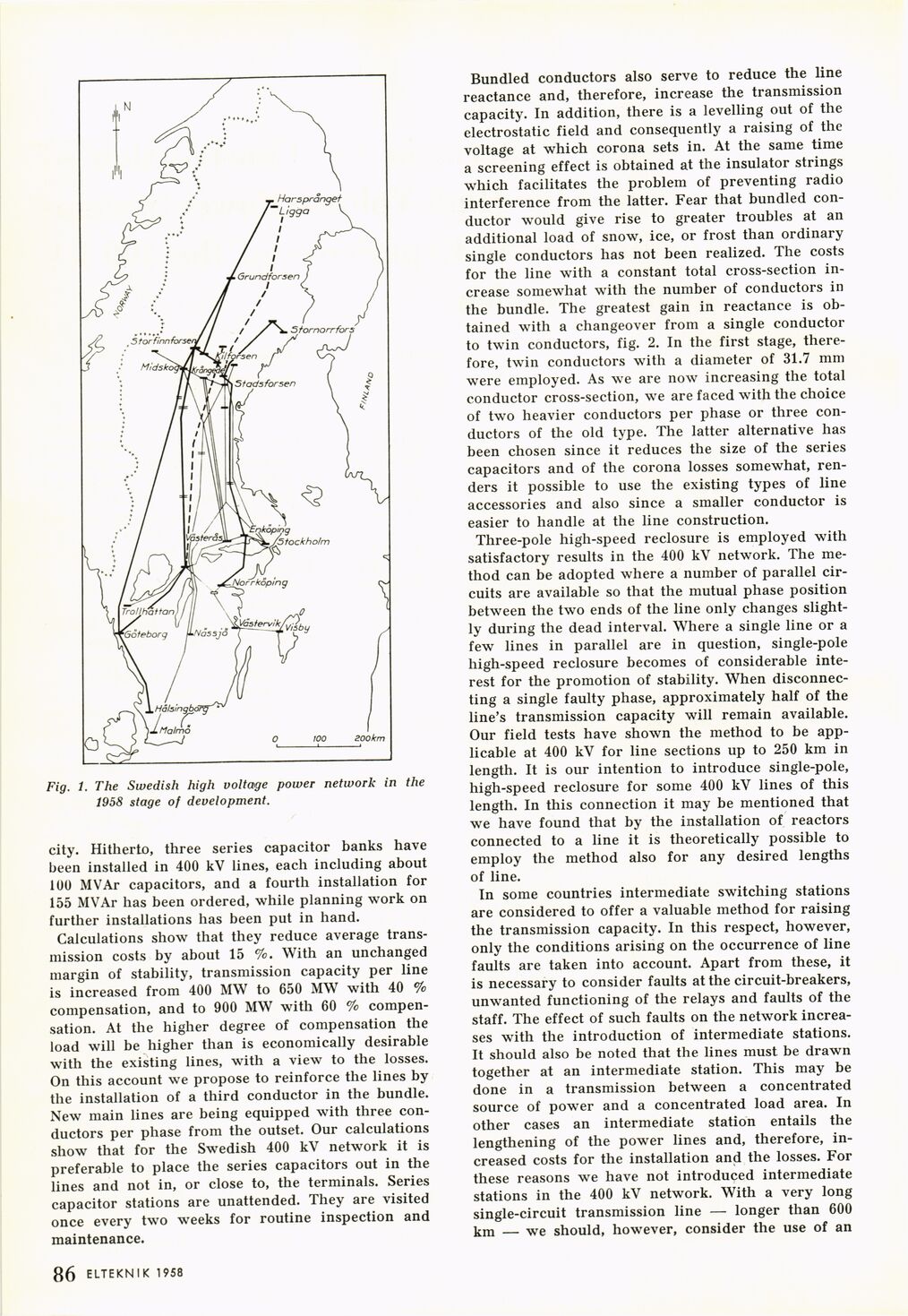
Fig. 1. The Swedish high volta>ge power network in the
1958 stage of development.
city. Hitherto, three series capacitor banks have
been installed in 400 kV lines, each including about
100 MVAr capacitors, and a fourth installation for
155 MVAr has been ordered, while planning work on
further installations has been put in hand.
Calculations show that they reduce average
transmission costs by about 15 %. With an unchanged
margin of stability, transmission capacity per line
is increased from 400 MW to 650 MW with 40 %
compensation, and to 900 MW with 60 %
compensation. At the higher degree of compensation the
load will be higher than is economically desirable
with the existing lines, with a view to the losses.
On this account we propose to reinforce the lines by
the installation of a third conductor in the bundle.
New main lines are being equipped with three
conductors per phase from the outset. Our calculations
show that for the Swedish 400 kV network it is
preferable to place the series capacitors out in the
lines and not in, or close to, the terminals. Series
capacitor stations are unattended. They are visited
once every two weeks for routine inspection and
maintenance.
Bundled conductors also serve to reduce the line
reactance and, therefore, increase the transmission
capacity. In addition, there is a levelling out of the
electrostatic field and consequently a raising of the
voltage at which corona sets in. At the same time
a screening effect is obtained at the insulator strings
which facilitates the problem of preventing radio
interference from the latter. Fear that bundled
conductor would give rise to greater troubles at an
additional load of snow, ice, or frost than ordinary
single conductors has not been realized. The costs
for the line with a constant total cross-section
increase somewhat with the number of conductors in
the bundle. The greatest gain in reactance is
obtained with a changeover from a single conductor
to twin conductors, fig. 2. In the first stage,
therefore, twin conductors with a diameter of 31.7 mm
were employed. As we are now increasing the total
conductor cross-section, we are faced with the choice
of two heavier conductors per phase or three
conductors of the old type. The latter alternative has
been chosen since it reduces the size of the series
capacitors and of the corona losses somewhat,
renders it possible to use the existing types of line
accessories and also since a smaller conductor is
easier to handle at the line construction.
Three-pole high-speed reclosure is employed with
satisfactory results in the 400 kV network. The
method can be adopted where a number of parallel
circuits are available so that the mutual phase position
between the two ends of the line only changes
slightly during the dead interval. Where a single line or a
few lines in parallel are in question, single-pole
high-speed reclosure becomes of considerable
interest for the promotion of stability. When
disconnecting a single faulty phase, approximately half of the
line’s transmission capacity will remain available.
Our field tests have shown the method to be
applicable at 400 kV for line sections up to 250 km in
length. It is our intention to introduce single-pole,
high-speed reclosure for some 400 kV lines of this
length. In this connection it may be mentioned that
we have found that by the installation of reactors
connected to a line it is theoretically possible to
employ the method also for any desired lengths
of line.
In some countries intermediate switching stations
are considered to offer a valuable method for raising
the transmission capacity. In this respect, however,
only the conditions arising on the occurrence of line
faults are taken into account. Apart from these, it
is necessary to consider faults at the circuit-breakers,
unwanted functioning of the relays and faults of the
staff. The effect of such faults on the network
increases with the introduction of intermediate stations.
It should also be noted that the lines must be drawn
together at an intermediate station. This may be
done in a transmission between a concentrated
source of power and a concentrated load area. In
other cases an intermediate station entails the
lengthening of the power lines and, therefore,
increased costs for the installation and the losses. For
these reasons we have not introduced intermediate
stations in the 400 kV network. With a very long
single-circuit transmission line — longer than 600
km — we should, however, consider the use of an
1 86 ELTEKN I K 1958
<< prev. page << föreg. sida << >> nästa sida >> next page >>