
Full resolution (JPEG) - On this page / på denna sida - 1958, H. 7 - Microwave Load Isolators and Related Components, by Per Erik Ljung
<< prev. page << föreg. sida << >> nästa sida >> next page >>
Below is the raw OCR text
from the above scanned image.
Do you see an error? Proofread the page now!
Här nedan syns maskintolkade texten från faksimilbilden ovan.
Ser du något fel? Korrekturläs sidan nu!
This page has never been proofread. / Denna sida har aldrig korrekturlästs.
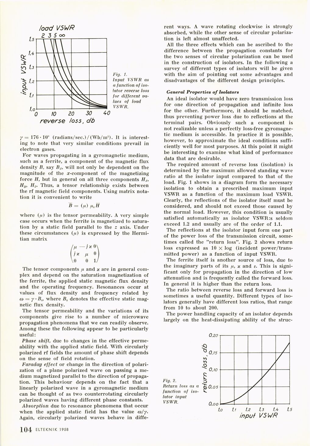
Fig. 1.
Input VSWR as
a function of
isolator reverse toss
for different
values of load
VSWR.
y — 17(3 • 10° (radians/sec.)/(Wb/m2). It is
interesting to note that very similar conditions prevail in
electron gases.
For waves propagating in a gyromagnetic medium,
such as a ferrite, a component of the magnetic flux
density B, say Bx, will not only be dependent on the
magnitude of the a>component of the magnetizing
force H, but in general on all three components Hr,
H}/, Hz. Thus, a tensor relationship exists between
the rf magnetic field components. Using matrix
notation it is convenient to write
B = (ju) fi0 H
where (/u) is the tensor permeability. A very simple
case occurs when the ferrite is magnetized to
saturation by a static field parallel to the z axis. Under
these circumstances (/u) is expressed by the
Hermi-tian matrix
hi -jx 0\
\}x p 0
\o 0 1/
The tensor components /x and x are in general
complex and depend on the saturation magnetization of
the ferrite, the applied static magnetic flux density
and the operating frequency. Resonances occur at
values of flux density and frequency related by
to — y B0, where B0 denotes the effective static
magnetic flux density.
The tensor permeability and the variations of its
components give rise to a number of microwave
propagation phenomena that we can readily observe.
Among these the following appear to be particularly
useful:
Phase shift, due to changes in the effective
permeability with the applied static field. With circularly
polarized rf fields the amount of phase shift depends
on the sense of field rotation.
Faraday effect or change in the direction of
polarization of a plane polarized wave on passing a
medium magnetized parallel to the direction of
propagation. This behaviour depends on the fact that a
linearly polarized wave in a gyromagnetic medium
can be thought of as two counterrotating circularly
polarized waves having different phase constants.
Absorption due to resonance phenomena that occur
when the applied static field has the value co/y.
Again, circularly polarized waves behave in diffe-
rent ways. A wave rotating clockwise is strongly
absorbed, while the other sense of circular
polarization is left almost unaffected.
All the three effects which can be ascribed to the
difference between the propagation constants for
the two senses of circular polarization can be used
in the construction of isolators. In the following a
survey of different types of isolators will be given
with the aim of pointing out some advantages and
disadvantages of the different design principles.
General Properties of Isolators
An ideal isolator would have zero transmission loss
for one direction of propagation and infinite loss
for the other. Furthermore, it should be matched,
thus preventing power loss due to reflections at the
terminal pairs. Obviously such a component is
not realizable unless a perfectly loss-free
gyromagnetic medium is accessible. In practice it is possible,
however, to approximate the ideal conditions
sufficiently well for most purposes. At this point it might
be interesting to examine what kind of performance
data that are desirable.
The required amount of reverse loss (isolation) is
determined by the maximum allowed standing wave
ratio at the isolator input compared to that of the
load. Fig. 1 shows in a diagram form the necessary
isolation to obtain a prescribed maximum input
VSWR as a function of the maximum load VSWR.
Clearly, the reflections of the isolator itself must be
considered, and should not exceed those caused by
the normal load. However, this condition is usually
satisfied automatically as isolator VSWR:s seldom
exceed 1.2 and usually are of the order of 1.1.
The reflections at the isolator input form one part
of the power loss of the transmission circuit,
sometimes called the "return loss". Fig. 2 shows return
loss expressed as 10 X log (incident
power/trans-mitted power) as a function of input VSWR.
The ferrite itself is another source of loss, due to
the imaginary parts of its p,, x and This is
significant only for propagation in the direction of low
attenuation and is frequently called the forward loss.
In general it is higher than the return loss.
The ratio between reverse loss and forward loss is
sometimes a useful quantity. Different types of
isolators generally have different loss ratios, that range
from 10 to about 200.
The power handling capacity of an isolator depends
largely on the heat-dissipating ability of the struc-
Fig. 2.
Return loss as a
function of
isolator input
VSWR.
1 104 ELTEKN I K 1958
<< prev. page << föreg. sida << >> nästa sida >> next page >>