
Full resolution (JPEG) - On this page / på denna sida - 1958, H. 7 - Microwave Load Isolators and Related Components, by Per Erik Ljung
<< prev. page << föreg. sida << >> nästa sida >> next page >>
Below is the raw OCR text
from the above scanned image.
Do you see an error? Proofread the page now!
Här nedan syns maskintolkade texten från faksimilbilden ovan.
Ser du något fel? Korrekturläs sidan nu!
This page has never been proofread. / Denna sida har aldrig korrekturlästs.
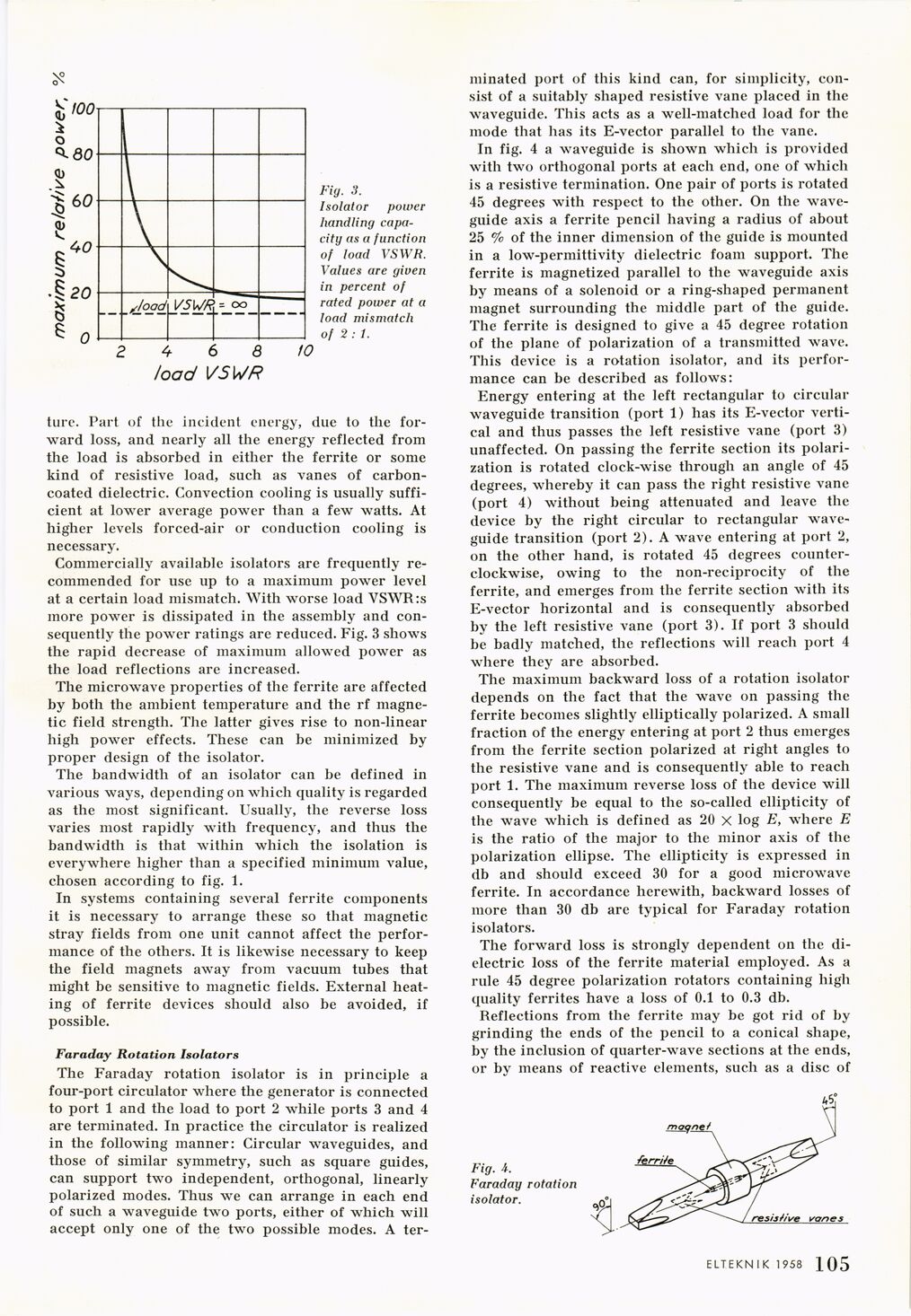
Fig. 3.
Isolator power
handling
capacity as a function
of load VSWR.
Values are given
in percent of
rated power at a
load mismatch
of 2 : t.
ture. Part of the incident energy, due to the
forward loss, and nearly all the energy reflected from
the load is absorbed in either the ferrite or some
kind of resistive load, such as vanes of
carbon-coated dielectric. Convection cooling is usually
sufficient at lower average power than a few watts. At
higher levels forced-air or conduction cooling is
necessary.
Commercially available isolators are frequently
recommended for use up to a maximum power level
at a certain load mismatch. With worse load VSWR:s
more power is dissipated in the assembly and
consequently the power ratings are reduced. Fig. 3 shows
the rapid decrease of maximum allowed power as
the load reflections are increased.
The microwave properties of the ferrite are affected
by both the ambient temperature and the rf
magnetic field strength. The latter gives rise to non-linear
high power effects. These can be minimized by
proper design of the isolator.
The bandwidth of an isolator can be defined in
various ways, depending on which quality is regarded
as the most significant. Usually, the reverse loss
varies most rapidly with frequency, and thus the
bandwidth is that within which the isolation is
everywhere higher than a specified minimum value,
chosen according to fig. 1.
In systems containing several ferrite components
it is necessary to arrange these so that magnetic
stray fields from one unit cannot affect the
performance of the others. It is likewise necessary to keep
the field magnets away from vacuum tubes that
might be sensitive to magnetic fields. External
heating of ferrite devices should also be avoided, if
possible.
Faraday Rotation Isolators
The Faraday rotation isolator is in principle a
four-port circulator where the generator is connected
to port 1 and the load to port 2 while ports 3 and 4
are terminated. In practice the circulator is realized
in the following manner: Circular waveguides, and
those of similar symmetry, such as square guides,
can support two independent, orthogonal, linearly
polarized modes. Thus we can arrange in each end
of such a waveguide two ports, either of which will
accept only one of the two possible modes. A ter-
minated port of this kind can, for simplicity,
consist of a suitably shaped resistive vane placed in the
waveguide. This acts as a well-matched load for the
mode that has its E-vector parallel to the vane.
In fig. 4 a waveguide is shown which is provided
with two orthogonal ports at each end, one of which
is a resistive termination. One pair of ports is rotated
45 degrees with respect to the other. On the
waveguide axis a ferrite pencil having a radius of about
25 % of the inner dimension of the guide is mounted
in a low-permittivity dielectric foam support. The
ferrite is magnetized parallel to the waveguide axis
by means of a solenoid or a ring-shaped permanent
magnet surrounding the middle part of the guide.
The ferrite is designed to give a 45 degree rotation
of the plane of polarization of a transmitted wave.
This device is a rotation isolator, and its
performance can be described as follows:
Energy entering at the left rectangular to circular
waveguide transition (port 1) has its E-vector
vertical and thus passes the left resistive vane (port 3)
unaffected. On passing the ferrite section its
polarization is rotated clock-wise through an angle of 45
degrees, whereby it can pass the right resistive vane
(port 4) without being attenuated and leave the
device by the right circular to rectangular
waveguide transition (port 2). A wave entering at port 2,
on the other hand, is rotated 45 degrees
counterclockwise, owing to the non-reciprocity of the
ferrite, and emerges from the ferrite section with its
E-vector horizontal and is consequently absorbed
by the left resistive vane (port 3). If port 3 should
be badly matched, the reflections will reach port 4
where they are absorbed.
The maximum backward loss of a rotation isolator
depends on the fact that the wave on passing the
ferrite becomes slightly elliptically polarized. A small
fraction of the energy entering at port 2 thus emerges
from the ferrite section polarized at right angles to
the resistive vane and is consequently able to reach
port 1. The maximum reverse loss of the device will
consequently be equal to the so-called ellipticity of
the wave which is defined as 20 X log E, where E
is the ratio of the major to the minor axis of the
polarization ellipse. The ellipticity is expressed in
db and should exceed 30 for a good microwave
ferrite. In accordance herewith, backward losses of
more than 30 db are typical for Faraday rotation
isolators.
The forward loss is strongly dependent on the
dielectric loss of the ferrite material employed. As a
rule 45 degree polarization rotators containing high
quality ferrites have a loss of 0.1 to 0.3 db.
Reflections from the ferrite may be got rid of by
grinding the ends of the pencil to a conical shape,
by the inclusion of quarter-wave sections at the ends,
or by means of reactive elements, such as a disc of
Fig.
Faradag rotation
isolator.
ELTEKNIK 1958 1 1 9
<< prev. page << föreg. sida << >> nästa sida >> next page >>