
Full resolution (JPEG) - On this page / på denna sida - 1958, H. 8 - The Transformer Ratio-arm Bridge, by Raymond Calvert
<< prev. page << föreg. sida << >> nästa sida >> next page >>
Below is the raw OCR text
from the above scanned image.
Do you see an error? Proofread the page now!
Här nedan syns maskintolkade texten från faksimilbilden ovan.
Ser du något fel? Korrekturläs sidan nu!
This page has never been proofread. / Denna sida har aldrig korrekturlästs.
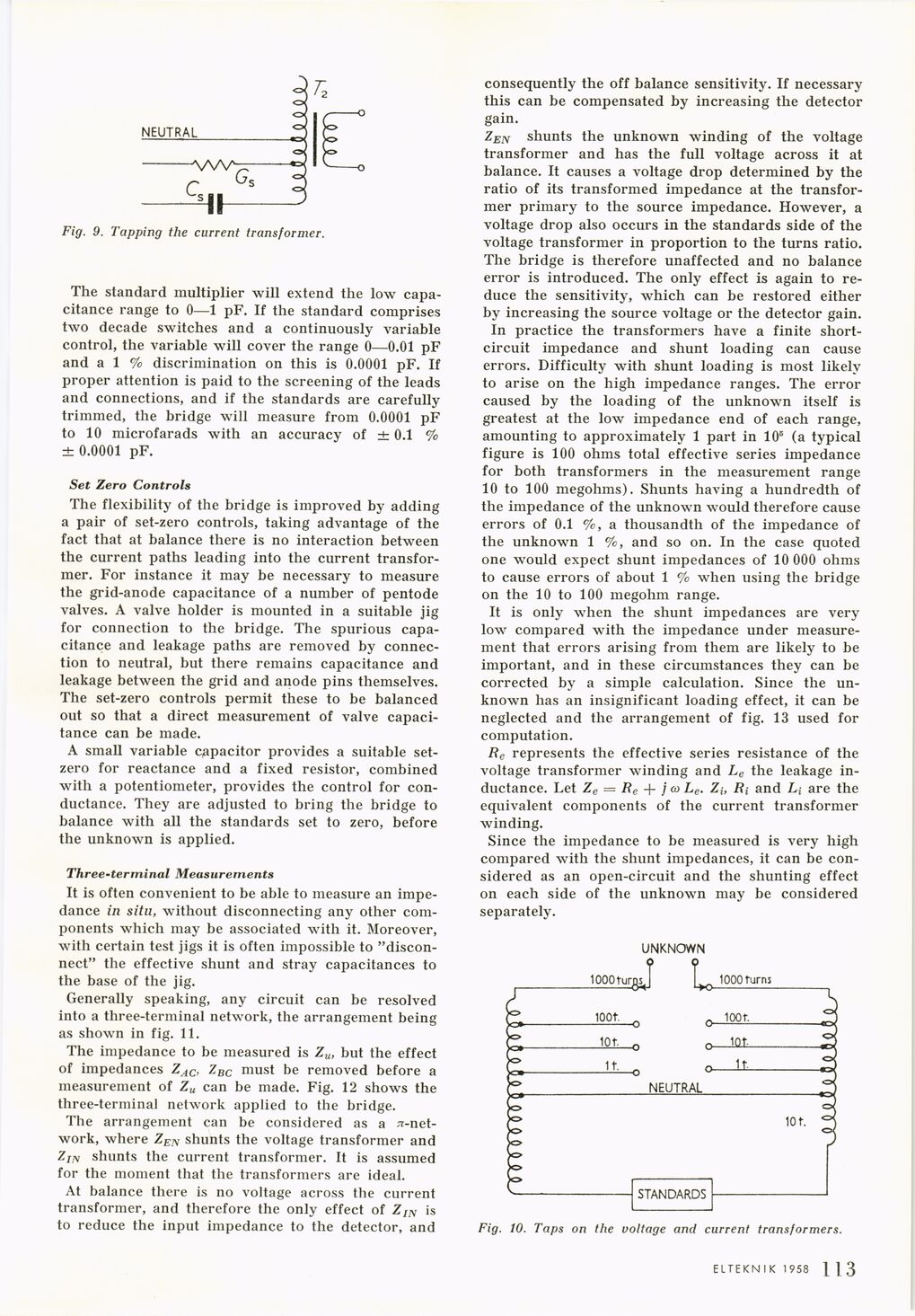
Fig. 9. Tapping the current transformer.
The standard multiplier will extend the low
capacitance range to 0—1 pF. If the standard comprises
two decade switches and a continuously variable
control, the variable will cover the range 0—0.01 pF
and a 1 % discrimination on this is 0.0001 pF. If
proper attention is paid to the screening of the leads
and connections, and if the standards are carefully
trimmed, the bridge will measure from 0.0001 pF
to 10 microfarads with an accuracy of ± 0.1 %
± 0.0001 pF.
Set Zero Controls
The flexibility of the bridge is improved by adding
a pair of set-zero controls, taking advantage of the
fact that at balance there is no interaction between
the current paths leading into the current
transformer. For instance it may be necessary to measure
the grid-anode capacitance of a number of pentode
valves. A valve holder is mounted in a suitable jig
for connection to the bridge. The spurious
capacitance and leakage paths are removed by
connection to neutral, but there remains capacitance and
leakage between the grid and anode pins themselves.
The set-zero controls permit these to be balanced
out so that a direct measurement of valve
capacitance can be made.
A small variable capacitor provides a suitable
set-zero for reactance and a fixed resistor, combined
with a potentiometer, provides the control for
conductance. They are adjusted to bring the bridge to
balance with all the standards set to zero, before
the unknown is applied.
Three-terminal Measurements
It is often convenient to be able to measure an
impedance in situ, without disconnecting any other
components which may be associated with it. Moreover,
with certain test jigs it is often impossible to
"disconnect" the effective shunt and stray capacitances to
the base of the jig.
Generally speaking, any circuit can be resolved
into a three-terminal network, the arrangement being
as shown in fig. 11.
The impedance to be measured is Zu, but the effect
of impedances ZAC, ZBC must be removed before a
measurement of Zu can be made. Fig. 12 shows the
three-terminal network applied to the bridge.
The arrangement can be considered as a
^-network, where ZEN shunts the voltage transformer and
ZIN shunts the current transformer. It is assumed
for the moment that the transformers are ideal.
At balance there is no voltage across the current
transformer, and therefore the only effect of ZIN is
to reduce the input impedance to the detector, and
consequently the off balance sensitivity. If necessary
this can be compensated by increasing the detector
gain.
ZEN shunts the unknown winding of the voltage
transformer and has the full voltage across it at
balance. It causes a voltage drop determined by the
ratio of its transformed impedance at the
transformer primary to the source impedance. However, a
voltage drop also occurs in the standards side of the
voltage transformer in proportion to the turns ratio.
The bridge is therefore unaffected and no balance
error is introduced. The only effect is again to
reduce the sensitivity, which can be restored either
by increasing the source voltage or the detector gain.
In practice the transformers have a finite
short-circuit impedance and shunt loading can cause
errors. Difficulty with shunt loading is most likely
to arise on the high impedance ranges. The error
caused by the loading of the unknown itself is
greatest at the low impedance end of each range,
amounting to approximately 1 part in 10® (a typical
figure is 100 ohms total effective series impedance
for both transformers in the measurement range
10 to 100 megohms). Shunts having a hundredth of
the impedance of the unknown would therefore cause
errors of 0.1 a thousandth of the impedance of
the unknown 1 %, and so on. In the case quoted
one would expect shunt impedances of 10 000 ohms
to cause errors of about 1 % when using the bridge
on the 10 to 100 megohm range.
It is only when the shunt impedances are very
low compared with the impedance under
measurement that errors arising from them are likely to be
important, and in these circumstances they can be
corrected by a simple calculation. Since the
unknown has an insignificant loading effect, it can be
neglected and the arrangement of fig. 13 used for
computation.
Re represents the effective series resistance of the
voltage transformer winding and Le the leakage
inductance. Let Ze = Re + j co Le. Zi, Ri and Li are the
equivalent components of the current transformer
winding.
Since the impedance to be measured is very high
compared with the shunt impedances, it can be
considered as an open-circuit and the shunting effect
on each side of the unknown may be considered
separately.
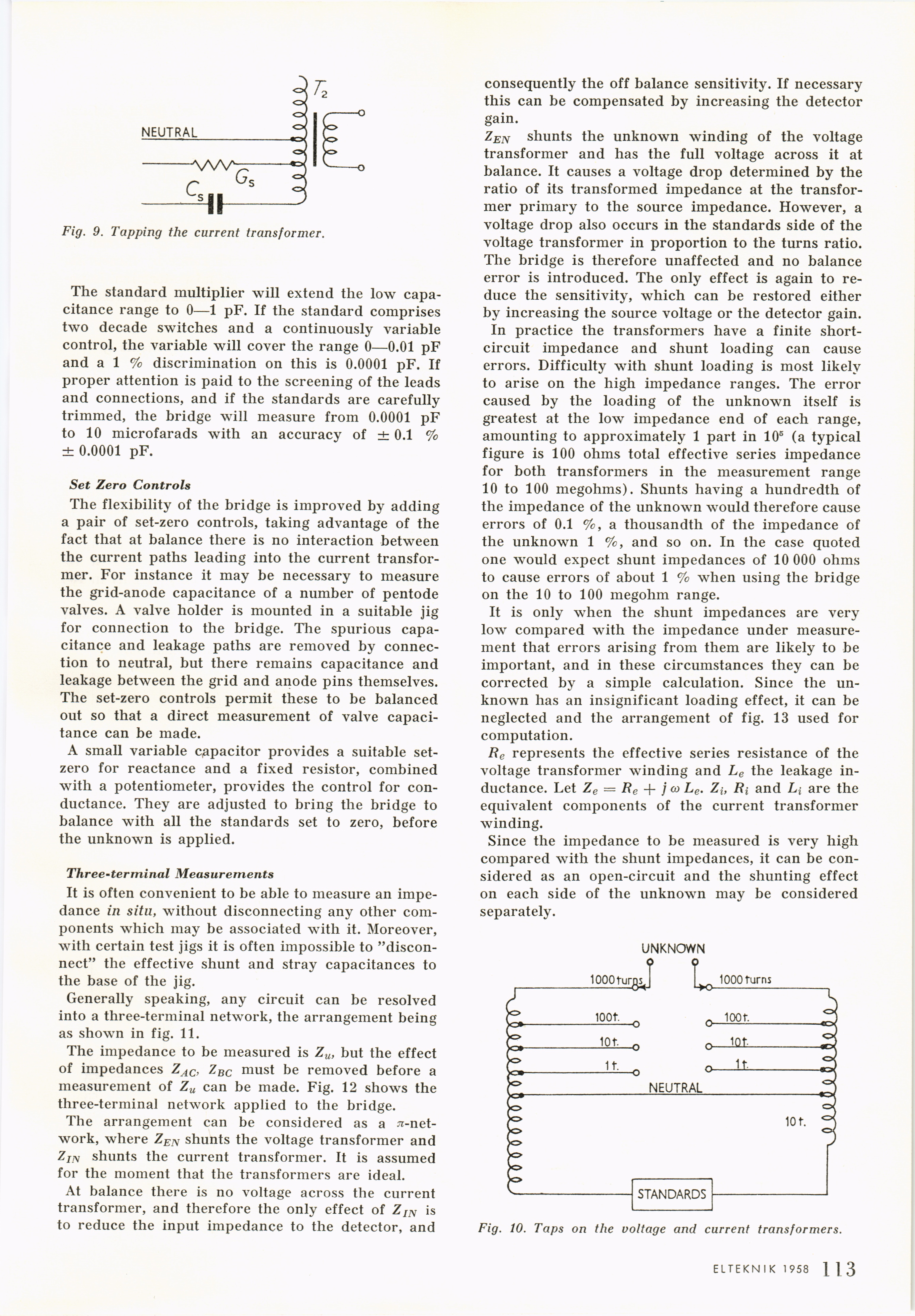
Fig. 10. Taps on the voltage and current transformers.
ELTEKNIK 1 958 1 ] 3
<< prev. page << föreg. sida << >> nästa sida >> next page >>