
Full resolution (JPEG) - On this page / på denna sida - 1958, H. 8 - The Transformer Ratio-arm Bridge, by Raymond Calvert
<< prev. page << föreg. sida << >> nästa sida >> next page >>
Below is the raw OCR text
from the above scanned image.
Do you see an error? Proofread the page now!
Här nedan syns maskintolkade texten från faksimilbilden ovan.
Ser du något fel? Korrekturläs sidan nu!
This page has never been proofread. / Denna sida har aldrig korrekturlästs.
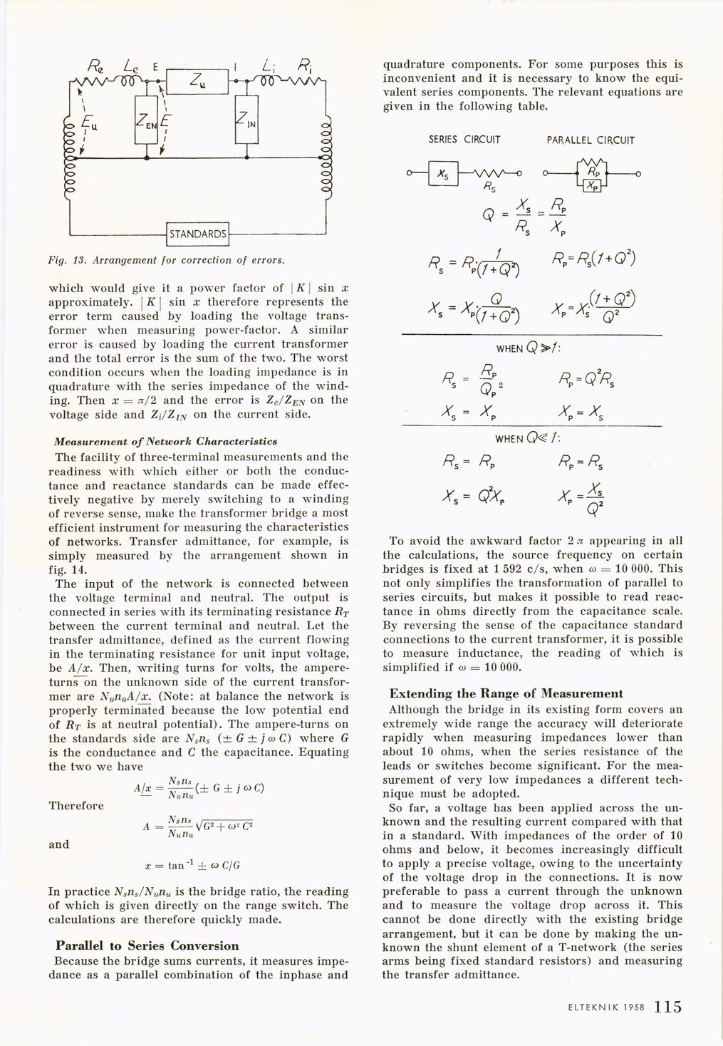
Fig. 13. Arrangement for correction of errors.
which would give it a power factor of | K | sin x
approximately. [ K | sin x therefore represents the
error term caused by loading the voltage
transformer when measuring power-factor. A similar
error is caused by loading the current transformer
and the total error is the sum of the two. The worst
condition occurs when the loading impedance is in
quadrature with the series impedance of the
winding. Then x = Jt/2 and the error is Ze/ZEN on the
voltage side and ZJZIN on the current side.
Measurement of Network Characteristics
The facility of three-terminal measurements and the
readiness with which either or both the
conductance and reactance standards can be made
effectively negative by merely switching to a winding
of reverse sense, make the transformer bridge a most
efficient instrument for measuring the characteristics
of networks. Transfer admittance, for example, is
simply measured by the arrangement shown in
fig. 14.
The input of the network is connected between
the voltage terminal and neutral. The output is
connected in series with its terminating resistance RT
between the current terminal and neutral. Let the
transfer admittance, defined as the current flowing
in the terminating resistance for unit input voltage,
be A/x. Then, writing turns for volts, the
ampere-turns on the unknown side of the current
transformer are NunuA/x. (Note: at balance the network is
properly terminated because the low potential end
of Rt is at neutral potential). The ampere-turns on
the standards side are Nsiis (± G ± j a> C) where G
is the conductance and C the capacitance. Equating
the two we have
Afx = ^(±G±jcoC)
—• /»aria
Therefore
and
A = ^G2 + CJ- C2
Nunu
x = tan"1 ± (o C/G
In practice Nsns/Nllnu is the bridge ratio, the reading
of which is given directly on the range switch. The
calculations are therefore quickly made.
Parallel to Series Conversion
Because the bridge sums currents, it measures
impedance as a parallel combination of the inphase and
quadrature components. For some purposes this is
inconvenient and it is necessary to know the
equivalent series components. The relevant equations are
given in the following table.
To avoid the awkward factor 2 n appearing in all
the calculations, the source frequency on certain
bridges is fixed at 1 592 c/s, when w = 10 000. This
not only simplifies the transformation of parallel to
series circuits, but makes it possible to read
reactance in ohms directly from the capacitance scale.
By reversing the sense of the capacitance standard
connections to the current transformer, it is possible
to measure inductance, the reading of which is
simplified if o> = 10 000.
Extending the Range of Measurement
Although the bridge in its existing form covers an
extremely wide range the accuracy will deteriorate
rapidly when measuring impedances lower than
about 10 ohms, when the series resistance of the
leads or switches become significant. For the
measurement of very low impedances a different
technique must be adopted.
So far, a voltage has been applied across the
unknown and the resulting current compared with that
in a standard. With impedances of the order of 10
ohms and below, it becomes increasingly difficult
to apply a precise voltage, owing to the uncertainty
of the voltage drop in the connections. It is now
preferable to pass a current through the unknown
and to measure the voltage drop across it. This
cannot be done directly with the existing bridge
arrangement, but it can be done by making the
unknown the shunt element of a T-network (the series
arms being fixed standard resistors) and measuring
the transfer admittance.
ELTEKNIK 1 958 1 ] 3
<< prev. page << föreg. sida << >> nästa sida >> next page >>