
Full resolution (JPEG) - On this page / på denna sida - 1959, H. 4 - Some Aspects on the Design and Use of the Helical Antenna, by göran Svennérus
<< prev. page << föreg. sida << >> nästa sida >> next page >>
Below is the raw OCR text
from the above scanned image.
Do you see an error? Proofread the page now!
Här nedan syns maskintolkade texten från faksimilbilden ovan.
Ser du något fel? Korrekturläs sidan nu!
This page has never been proofread. / Denna sida har aldrig korrekturlästs.
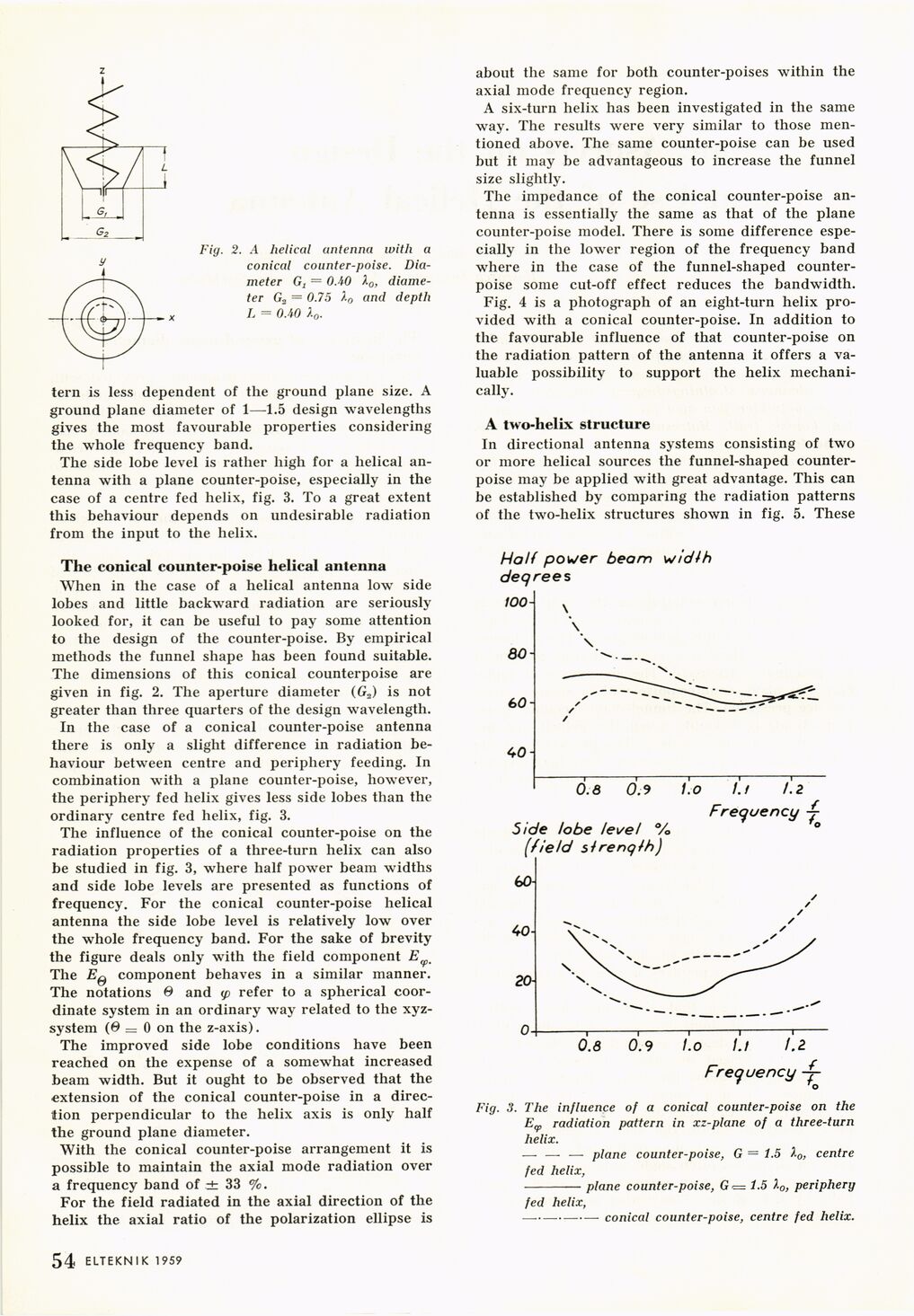
Fig. 2. A helical antenna with a
conical counter-poise.
Diameter Gx = OAO X0,
diameter G2 = 0.75 )-0 and depth
L = OAO X0.
tern is less dependent of the ground plane size. A
ground plane diameter of 1—1.5 design wavelengths
gives the most favourable properties considering
the whole frequency band.
The side lobe level is rather high for a helical
antenna with a plane counter-poise, especially in the
case of a centre fed helix, fig. 3. To a great extent
this behaviour depends on undesirable radiation
from the input to the helix.
The conical counter-poise helical antenna
When in the case of a helical antenna low side
lobes and little backward radiation are seriously
looked for, it can be useful to pay some attention
to the design of the counter-poise. By empirical
methods the funnel shape has been found suitable.
The dimensions of this conical counterpoise are
given in fig. 2. The aperture diameter (G2) is not
greater than three quarters of the design wavelength.
In the case of a conical counter-poise antenna
there is only a slight difference in radiation
behaviour between centre and periphery feeding. In
combination with a plane counter-poise, however,
the periphery fed helix gives less side lobes than the
ordinary centre fed helix, fig. 3.
The influence of the conical counter-poise on the
radiation properties of a three-turn helix can also
be studied in fig. 3, where half power beam widths
and side lobe levels are presented as functions of
frequency. For the conical counter-poise helical
antenna the side lobe level is relatively low over
the whole frequency band. For the sake of brevity
the figure deals only with the field component E(fm
The Eß component behaves in a similar manner.
The notations 0 and (p refer to a spherical
coordinate system in an ordinary way related to the
xyz-system (ß = 0 on the z-axis).
The improved side lobe conditions have been
reached on the expense of a somewhat increased
beam width. But it ought to be observed that the
extension of the conical counter-poise in a
direction perpendicular to the helix axis is only half
the ground plane diameter.
With the conical counter-poise arrangement it is
possible to maintain the axial mode radiation over
a frequency band of ± 33 %.
For the field radiated in the axial direction of the
helix the axial ratio of the polarization ellipse is
about the same for both counter-poises within the
axial mode frequency region.
A six-turn helix has been investigated in the same
way. The results were very similar to those
mentioned above. The same counter-poise can be used
but it may be advantageous to increase the funnel
size slightly.
The impedance of the conical counter-poise
antenna is essentially the same as that of the plane
counter-poise model. There is some difference
especially in the lower region of the frequency band
where in the case of the funnel-shaped
counterpoise some cut-off effect reduces the bandwidth.
Fig. 4 is a photograph of an eight-turn helix
provided with a conical counter-poise. In addition to
the favourable influence of that counter-poise on
the radiation pattern of the antenna it offers a
valuable possibility to support the helix
mechanically.
A two-helix structure
In directional antenna systems consisting of two
or more helical sources the funnel-shaped
counterpoise may be applied with great advantage. This can
be established by comparing the radiation patterns
of the two-helix structures shown in fig. 5. These
r
r
Fig. 3. The influence of a conical counter-poise on the
Ev radiation pattern in xz-plane of a three-turn
helix.
— — — plane counter-poise, G = 1.5 centre
fed helix,
-plane counter-poise, G*= 1.5 X0, periphery
fed helix,
conical counter-poise, centre fed helix.
ELTEKNIK 1959 1 54
<< prev. page << föreg. sida << >> nästa sida >> next page >>