
Full resolution (JPEG) - On this page / på denna sida - Back-Scattering Cross Section of Reactively Loaded Cylindrical Antennas, by Bengt-Olof Ås and Hans J. Schmitt
<< prev. page << föreg. sida << >> nästa sida >> next page >>
Below is the raw OCR text
from the above scanned image.
Do you see an error? Proofread the page now!
Här nedan syns maskintolkade texten från faksimilbilden ovan.
Ser du något fel? Korrekturläs sidan nu!
This page has never been proofread. / Denna sida har aldrig korrekturlästs.
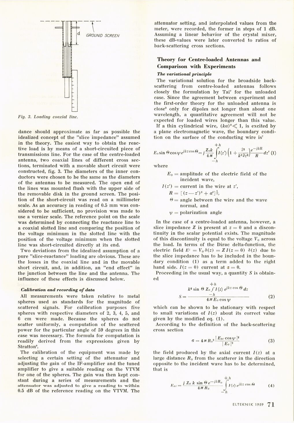
Fig. 3. Loading coaxial line.
dance should approximate as far as possible the
idealized concept of the "slice impedance" assumed
in the theory. The easiest way to obtain the
reactive load is by means of a short-circuited piece of
transmissions line. For the case of the centre-loaded
antenna, two coaxial lines of different cross
sections, terminated with a movable short circuit were
constructed, fig. 3. The diameters of the inner
conductors were chosen to be the same as the diameters
of the antennas to be measured. The open end of
the lines was mounted flush with the upper side of
the removable disk in the ground screen. The
position of the short-circuit was read on a millimeter
scale. As an accuracy in reading of 0.5 mm was
considered to be sufficient, no provision was made to
use a vernier scale. The reference point on the scale
was determined by connecting the reactance line to
a coaxial slotted line and comparing the position of
the voltage minimum in the slotted line with the
position of the voltage minimum when the slotted
line was short-circuited directly at its end.
Two deviations from the idealized assumption of a
pure "slice-reactance" loading are obvious. These are
the losses in the coaxial line and in the movable
short circuit, and, in addition, an "end effect" in
the junction between the line and the antenna. The
influence of these effects is discussed below.
Calibration and recording of data
All measurements were taken relative to metal
spheres used as standards for the magnitude of
scattered signals. For calibration purposes five
spheres with respective diameters of 2, 3, 4, 5, and
6 cm were made. Because the spheres do not
scatter uniformly, a computation of the scattered
power for the particular angle of 59 degrees in this
case was necessary. The formula for computation is
readily derived from the expressions given by
Stratton".
The calibration of the equipment was made by
selecting a certain setting of the attenuator and
adjusting the gain of the IF-amplifier and the tuned
amplifier to give a suitable reading on the VTVM
for one of the spheres. The gain was then kept
constant during a series of measurements and the
attenuator "was adjusted to give a reading to within
0.5 dB of the reference reading on the VTVM. The
attenuator setting, and interpolated values from the
meter, were recorded, the former in steps of 1 dB.
Assuming a linear behavior of the crystal mixer,
these dB-values were later converted to ratios of
back-scattering cross sections.
Theory for Centre-loaded Antennas and
Comparison with Experiments
The variational principle
The variational solution for the broadside
back-scattering from centre-loaded antennas follows
closely the formulation by Tai7 for the unloaded
case. Since the agreement between experiment and
the first-order theory for the unloaded antenna is
close3 only for dipoles not longer than about one
wavelength, a quantitative agreement will not be
expected for loaded wires longer than this value.
If a thin cylindrical wire, (ka)2<^ 1, is excited by
a plane electromagnetic wave, the boundary
condition on the surface of the conducting wire is7
+ h
E0s\nOcosy)eikzcos°
-’SH
i +
32 y-ikR
A-2 dz2 1 R
dz’ (1)
-h
where
E0 = amplitude of the electric field of the
incident wave,
I(z’) = current in the wire at z’,
R = [Cr — z’V- + a2]i
6 = angle between the wire and the wave
normal, and
y = polarization angle
In the case of a centre-loaded antenna, however, a
slice impedance Z is present at z = 0 and a
discontinuity in the scalar potential exists. The magnitude
of this discontinuity is equal to the voltage V0 across
the load. In terms of the Dirac delta-function, the
electric field E- = V0 8 (z) = ZI(z = 0) d(z) due to
the slice impedance has to be included in the
boundary condition (1) as a term added to the right
hand side. I(z = 0) current at z = 0.
Proceeding in the usual way, a quantity S is
obtained
+ h
k* sin 6 Zofl[z) eikzcos°dz
S=-I^Tp–(2)
4 Jt Eo eos rp
which can be shown to be stationary with respect
to small variations of /(z) about its correct value
given by the modified eq. (1).
According to the definition of the back-scattering
cross section
o - 4 tf Ro2
I Esc COS l/J [2
Eo I2
(3)
the field produced by the axial current I{z) at a
large distance R0 from the scatterer in the direction
opposite to the incident wave has to be determined,
that is
j Zo k sin e e~jkR<
in Rö
+.h
I(z) e’kz cos A
(4)
- h
ELTEKN IK 1959 71 0]
<< prev. page << föreg. sida << >> nästa sida >> next page >>