
Full resolution (JPEG) - On this page / på denna sida - On the Temperature Margins of a Transistor-Driven Coincident Current Ferrite Core Memory, by Jan-Rustan Törnquist
<< prev. page << föreg. sida << >> nästa sida >> next page >>
Below is the raw OCR text
from the above scanned image.
Do you see an error? Proofread the page now!
Här nedan syns maskintolkade texten från faksimilbilden ovan.
Ser du något fel? Korrekturläs sidan nu!
This page has never been proofread. / Denna sida har aldrig korrekturlästs.
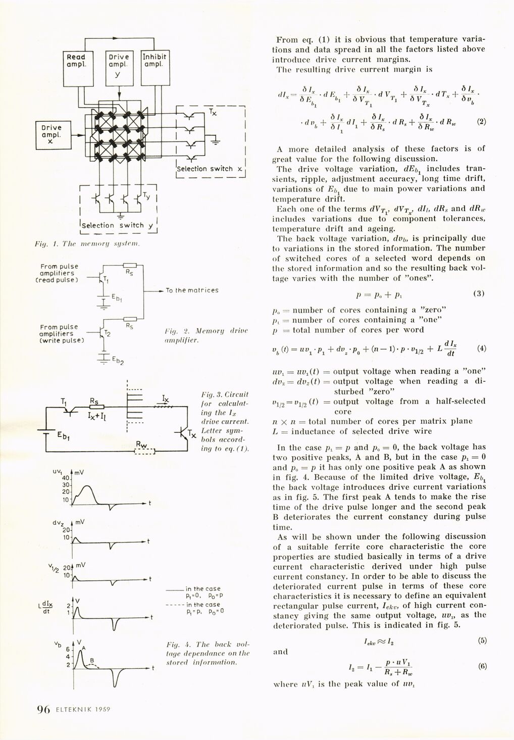
Fig. 1. The memory ay stem.
Fig. 2. Memory drive
amplifier.
Fig. 3. Circuit
for
calculating the lx
drive current.
Letter
symbols according to eq. (1).
Fig. A. The back
voltage dependance on the
stored information.
From eq. (1) it is obvious that temperature
variations and data spread in all the factors listed above
introduce drive current margins.
The resulting drive current margin is
dL. =
ölx
à K , „ fi /
dE. + . / dVT + v
hi <> Vr„ >\ oV
, , 01 r ,, , àlx
d"y+&fd’i+öt
i s
d Rs +
Tx
dlx
f>R„
d Tx -f
dR„
tlx
ÖV.
(2)
A more detailed analysis of these factors is of
great value for the following discussion.
The drive voltage variation, dE/>, includes
transients, ripple, adjustment accuracy, long time drift,
variations of E& due to main power variations and
temperature drift.
Each one of the terms dVTi, dVrx, dli, dRs and dR,r
includes variations due to component tolerances,
temperature drift and ageing.
The back voltage variation, dv/„ is principally due
to variations in the stored information. The number
of switched cores of a selected word depends on
the stored information and so the resulting back
voltage varies with the number of "ones".
V = A. + Pi (3)
/)„ — number of cores containing a "zero"
/>, = number of cores containing a "one"
[> = total number of cores per word
dlx
vb W = uvi-Pl + dvz-po + (n- I)- p • vV2 + L — (4)
m\ = iiVi(t) — output voltage when reading a "one"
dvz = dvz(t) = output voltage when reading a
disturbed "zero"
p1/2 = u1/2(0 = output voltage from a half-selected
core
n x ii = total number of cores per matrix plane
L = inductance of selected drive wire
Tn the case pt = p and p0 = 0, the back voltage has
two positive peaks, A and B, but in the case pt = 0
and p0 = p it has only one positive peak A as shown
in fig. 4. Because of the limited drive voltage, E^
the back voltage introduces drive current variations
as in fig. 5. The first peak A tends to make the rise
time of the drive pulse longer and the second peak
B deteriorates the current constancy during pulse
time.
As will be shown under the following discussion
of a suitable ferrite core characteristic the core
properties are studied basically in terms of a drive
current characteristic derived under high pulse
current constancy. In order to be able to discuss the
deteriorated current pulse in terms of these core
characteristics it is necessary to define an equivalent
rectangular pulse current, Iekv> of high current
constancy giving the same output voltage, uvu as the
deteriorated pulse. This is indicated in fig. 5.
and
h = l i
1ekv ^ 12
P-UV 1
Rs + flu,
where ttV, is the peak value of uv,
(5)
(fi)
.96 ELTEKNIK 1959
<< prev. page << föreg. sida << >> nästa sida >> next page >>