
Full resolution (JPEG) - On this page / på denna sida - Optical Feedback — A Method of Stabilizing the D. C. Conditions of Transistor Amplifiers, by Ragnar Forshufvud and Olov Rydgård - Lärobok i högspänningsteknik, av J Fryxell

<< prev. page << föreg. sida << >> nästa sida >> next page >>
Below is the raw OCR text
from the above scanned image.
Do you see an error? Proofread the page now!
Här nedan syns maskintolkade texten från faksimilbilden ovan.
Ser du något fel? Korrekturläs sidan nu!
This page has never been proofread. / Denna sida har aldrig korrekturlästs.
close together, and ambient light was screened off.
The amplifier contained only five components, of
which the bulb is the largest, fig. 3.
The temperature dependency of the emitter current
of the second stage is shown in fig. 4. The current
was measured as a function of ambient temperature
for the stabilized circuit (curve A) and with the
photo-resistor replaced by a constant resistor (curve
B).
The experimental amplifier had an input
impedance of 2.5 kiloohms and an output impedance of
35 ohms. The amplification was 54 dB with a load
impedance of 35 ohms. The upper frequency limit
is set by the transistor OC 74 — the current
amplification cut-off frequency being about 15 kHz in the
common-emitter connection. Also a lower frequency
limit exists, caused by the negative feedback at low
frequencies. However, the amplification was
constant down to 20 Hz. Measurement facilities for lower
frequencies were not available. No thorough
investigation regarding influence of component spread was
made.
Danger of self-oscillation
The total phase-shift in lamp plus photo-resistor
may exceed 180° at very low frequencies. Transistor
samples with very high current amplification
factors made the amplifier oscillate at 2—3 Hz.
Self-oscillation can be avoided by using transistors with
narrow tolerances. The transistor OC 45, chosen for
having a low collector back current, has a current
amplification factor of between 25 and 125. Another
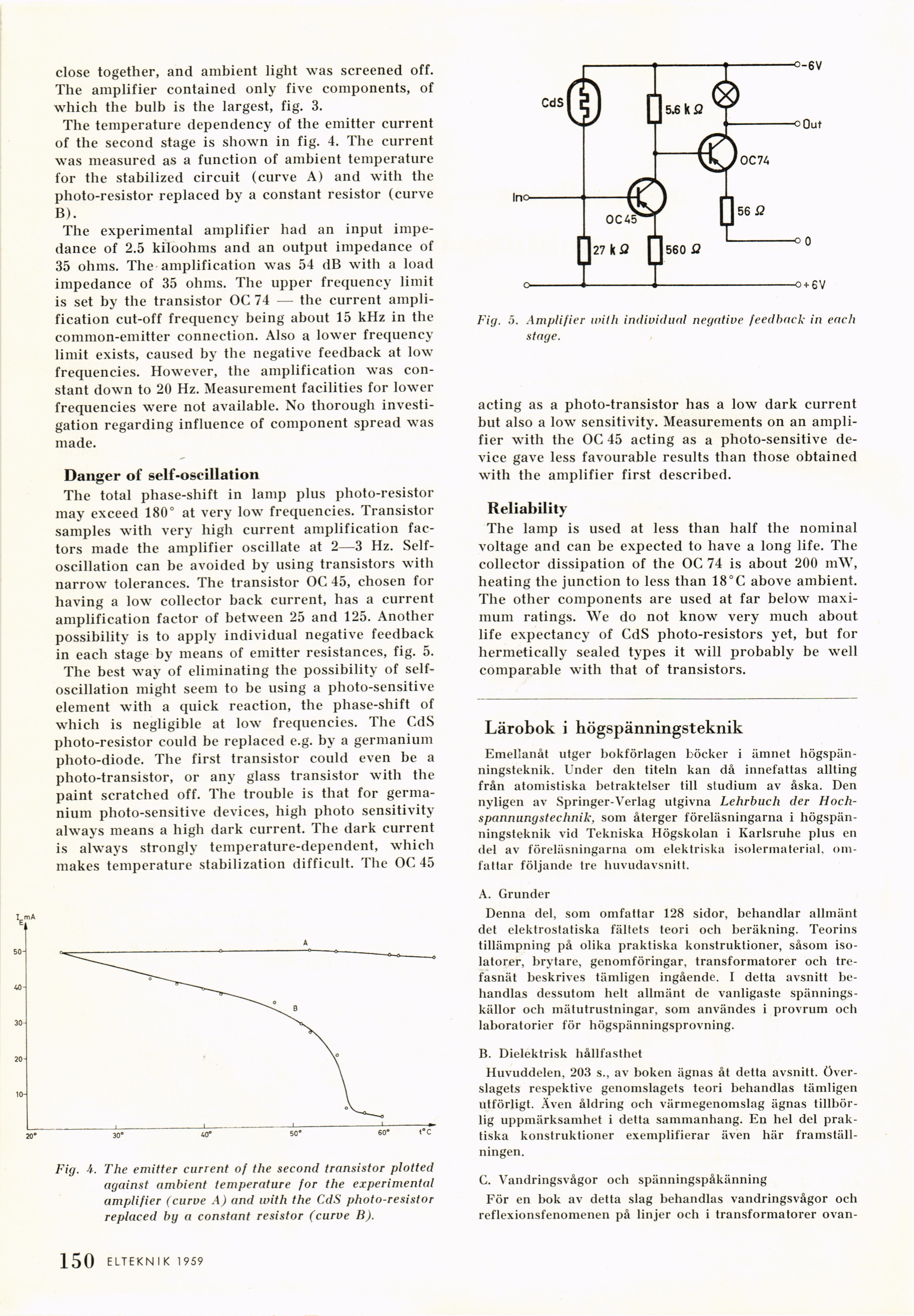
possibility is to apply individual negative feedback
in each stage by means of emitter resistances, fig. 5.
The best way of eliminating the possibility of
self-oscillation might seem to be using a photo-sensitive
element with a quick reaction, the phase-shift of
which is negligible at low frequencies. The CdS
photo-resistor could be replaced e.g. by a germanium
photo-diode. The first transistor could even be a
photo-transistor, or any glass transistor with the
paint scratched off. The trouble is that for
germanium photo-sensitive devices, high photo sensitivity
always means a high dark current. The dark current
is always strongly temperature-dependent, which
makes temperature stabilization difficult. The OC 45
mA
Fig. 4. The emitter current of the second transistor plotted
against ambient temperature for the experimental
amplifier (curve A) and with the CdS photo-resistor
replaced by a constant resistor (curve B).
Fig. 5. Amplifier with individual negative feedback in each
stage.
acting as a photo-transistor has a low dark current
but also a low sensitivity. Measurements on an
amplifier with the OC 45 acting as a photo-sensitive
device gave less favourable results than those obtained
with the amplifier first described.
Reliability
The lamp is used at less than half the nominal
voltage and can be expected to have a long life. The
collector dissipation of the OC 74 is about 200 mW,
heating the junction to less than 18°C above ambient.
The other components are used at far below
maximum ratings. We do not know very much about
life expectancy of CdS photo-resistors yet, but for
hermetically sealed types it will probably be well
comparable with that of transistors.
Lärobok i högspänningsteknik
Emellanåt utger bokförlagen böcker i ämnet
högspänningsteknik. Under den titeln kan då innefattas allting
från atomistiska betraktelser till studium av åska. Den
nyligen av Springer-Verlag utgivna Lehrbuch der
Hoch-spannungsteclinik, som återger föreläsningarna i
högspänningsteknik vid Tekniska Högskolan i Karlsruhe pius en
del av föreläsningarna om elektriska isolermaterial,
omfattar följande tre huvudavsnitt.
A. Grunder
Denna del, som omfattar 128 sidor, behandlar allmänt
det elektrostatiska fältets teori och beräkning. Teorins
tillämpning på olika praktiska konstruktioner, såsom
isolatorer, brytare, genomföringar, transformatorer och
trefasnät beskrives tämligen ingående. I detta avsnitt
behandlas dessutom helt allmänt de vanligaste
spänningskällor och mätutrustningar, som användes i provrum och
laboratorier för högspänningsprovning.
B. Dielektrisk hållfasthet
Huvuddelen, 203 s., av boken ägnas åt detta avsnitt,
överslagets respektive genomslagets teori behandlas tämligen
utförligt. Även åldring och värmegenomslag ägnas
tillbörlig uppmärksamhet i detta sammanhang. En hel del
praktiska konstruktioner exemplifierar även här
framställningen.
G. Vandringsvågor och spänningspåkänning
För en bok av detta slag behandlas vandringsvågor och
reflexionsfenomenen på linjer och i transformatorer ovan-
.150 ELTEKNIK 1959
<< prev. page << föreg. sida << >> nästa sida >> next page >>