
Full resolution (JPEG) - On this page / på denna sida - 1958, H. 4 - An Insulated Cable for Heavy Power Transmission, by Bror Hansson

<< prev. page << föreg. sida << >> nästa sida >> next page >>
Below is the raw OCR text
from the above scanned image.
Do you see an error? Proofread the page now!
Här nedan syns maskintolkade texten från faksimilbilden ovan.
Ser du något fel? Korrekturläs sidan nu!
This page has never been proofread. / Denna sida har aldrig korrekturlästs.
sion of a fault was exposed to double the rated
voltage, i.e. 2 X 500, then the dielectric losses near the
conductor would be
(24255Q0)!!-5.3 W/dras = 29 W/dm3
if 5.3 W/dm3 are the dielectric losses near the
conductor at 425 kV, fig. 8.
If these 29 W/dm3 for the dielectric losses near the
conductor are compared with the copper losses 21
W/dm3 for 1 000 amps and 900 mm2, then it becomes
apparent how important it is to reduce these
dielectric losses.
Graded insulation seems only indicated where high
d.c. and impulse voltages are feared. Present
protective devices are so improved that it now seems
permissible to ignore the impulse strength. If
sufficient care is taken to reach the highest possible a.c.
strength, the impulse strength will be taken care of
simultanously and grading of the insulation seems
not only unnecessary but rather dangerous, if we
want to make a cable for as high rated voltage as
possible.
Thus at the surface of the conductor everything
which is dangerous to the insulation is crowded
together. Here the dielectric losses are highest,
extremely high, here we have the copper losses, here
the dielectric stress is highest and here the heat
insulation is perfect.
If a cooling system could be conceived which could
remove the losses from these dangerous regions,
which would lower the temperature of the cables
interior and which, moreover, if a dangerous
over-voltage should strike the cable and damage the oil,
would act as a rejuvenator, transport stressed and
perhaps damaged oil to less dangerous regions and
supply new perfect insulating liquid to the region
of danger, then a greatly improved cable would be
conceived. If it finally was such that it raised the
pressure of the insulating liquid, especially at the
places where the dielectric stresses and the
temperature is highest, and lastly if this pressure was only
Table i. Tests on cable model. Temperature 15°C,
insulation thickness 5 mm, oil viscosity see fig. 9.
Paper quality Difference of Radial
Thickness Density oil pressure oil flow
of each paper
mm kp/cnr cm3/h, m cable
0.04 0.9 6 43
0.13 0.7 2 270
Table 2. Tests on 425 kV cable, 900 mm2, fig. lb.
Cable length 1 000 m, insulation thickness 28 mm,
temperature 15°C, oil viscosity see fig. 9.
Direction of Difference of Oil
oil flow oil pressure flow
kp/cm2 dm3/h
Axial, centre channel..... ......... 4 40
Axial, lead channels ..... ......... 4 1.9
Radial .................. ......... 4 28
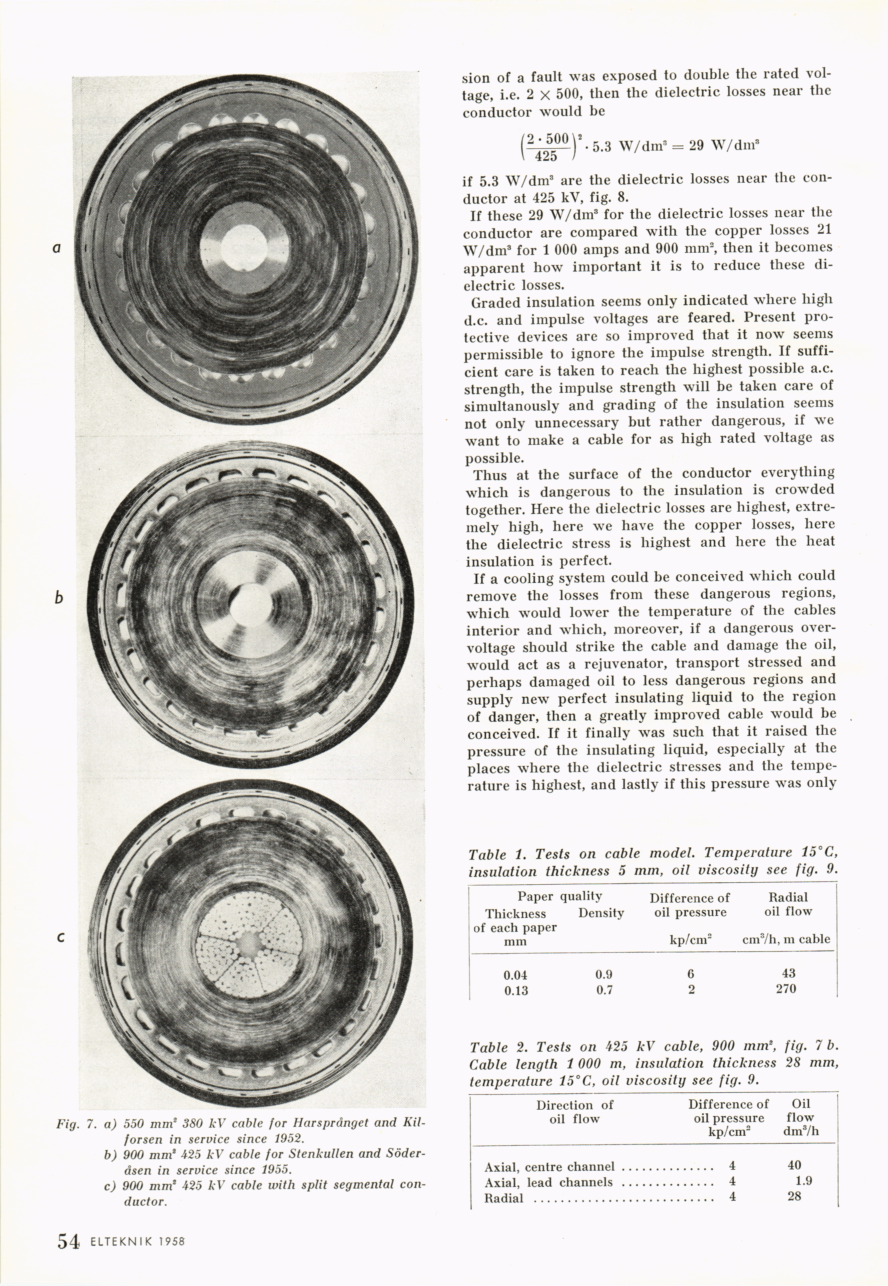
Fig. 7. a) 550 mm2 380 kV cable for Harsprånget and
Kil-forsen in service since 1952.
b) 900 mm2 425 kV cable for Stenkullen and
Söderåsen in service since 1955.
c) 900 mm2 425 kV cable with split segmental
conductor.
ELTEKNIK 1958
<< prev. page << föreg. sida << >> nästa sida >> next page >>