
Full resolution (JPEG) - On this page / på denna sida - 1958, H. 7 - The Quarter-Wave Dipole, by Bengt Josephson

<< prev. page << föreg. sida << >> nästa sida >> next page >>
Below is the raw OCR text
from the above scanned image.
Do you see an error? Proofread the page now!
Här nedan syns maskintolkade texten från faksimilbilden ovan.
Ser du något fel? Korrekturläs sidan nu!
This page has never been proofread. / Denna sida har aldrig korrekturlästs.
Fig. 7.
Twin-line shortened
dipole.
r- v
z*
h - kit
V’lZi,
(to)
(11)
where
Zfi = radiation impedance of the antenna conductors
connected in parallel
Zs — input impedance between the antenna
conductors
Equations (8) — (11) give the antenna impedance
4 Zi, Zg + Zs, (4 Zd + k Zb)
4 Zb + 4 Zd + (2 - k)Z., { ~>
lf Zi, or Zs have resistance components this results
in a power loss. It is then of interest to determine the
efficiency of the antenna. The input power is
P.n=~’Rc{z}
and the power loss
l/’2 11/ _
Pf= wRc[ i + Hcw
AV = JZJi
Pin Rc{Z}
1 V
T
Re[Zb)
Zb"’
+
V - V’ - Re[Zs)
W -
V
(15)
(14)
(15)
Hence the efficiency
n = 1 - pft Pin (lti)
The voltage ratios in (15) arc calculated from
equations (8)—(11).
The formulas (12) and (15) allow an investigation
of the possibilities of broadbanding a folded dipole
with the aid of load impedances located as in
figure 12.
Symmetrical Antenna
In the case examined below the antenna consists
of two equal wires, and thus k = 1. The general and
rather complicated formulas may then be simplified
with the aid of the following substitutions:
in = 2 Zb + Zs{1
ii =■ |2 Zb + 4 Zd\
j) = |4 Za — Z, |s
(17)
(18)
(19)
I sing the notations Z = R + jX, Z[> = Ru + jXt,, and
so on, the following expressions for impedance and
efficiency of the symmetrical antenna have been
deduced:
R
4 in Ih + ii R, + p R/,
2 in ’+ 2 ii — i>
4 ni Xd + ii + p Xb
2 ni + 2 ii — p
1
, ~n R~s~+P Rh
(20)
(21)
(22)
4 ni Rd
These formulas are suitable for numerical
calculations.
To determine the radiation impedance Zj, the
radius of a round wire is calculated, which is
equivalent to the two antenna wires connected in parallel.
According to Sclielkunoff this radius is I ad, where
(I is the centre distance and a the radius of the wires.
Then Zj as a function of frequency is given in the
curves of Hallen1 or Brown and Woodward’.
Resistance-loaded Short-wave Antenna
There are great difficulties in designing broadband
antennas for the short-wave range, which do not
take up excessive space. An antenna which seems
attractive is described by Williams3. It is a folded
dipole loaded with a resistance 2 Z^ = GOO ohms, and
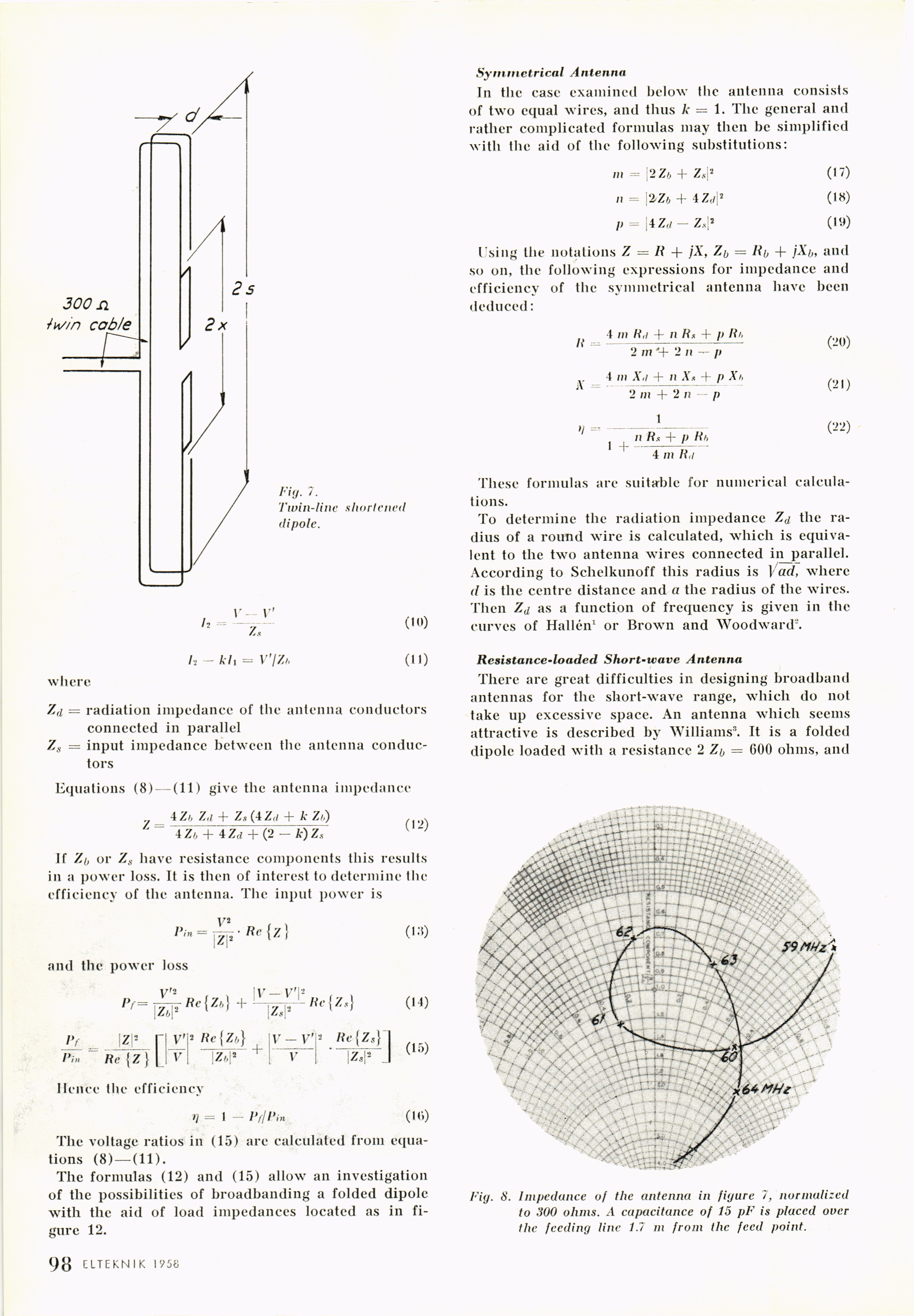
Fig. 8. Impedance of the antenna in figure 7, normalized
to 300 ohms. A capacitance of 15 pF is placed over
the feeding line 1.7 m from the feed point.
1 98 ELTEKN I K 1958
<< prev. page << föreg. sida << >> nästa sida >> next page >>