
Full resolution (JPEG) - On this page / på denna sida - 1958, H. 8 - The Transformer Ratio-arm Bridge, by Raymond Calvert
<< prev. page << föreg. sida << >> nästa sida >> next page >>
Below is the raw OCR text
from the above scanned image.
Do you see an error? Proofread the page now!
Här nedan syns maskintolkade texten från faksimilbilden ovan.
Ser du något fel? Korrekturläs sidan nu!
This page has never been proofread. / Denna sida har aldrig korrekturlästs.
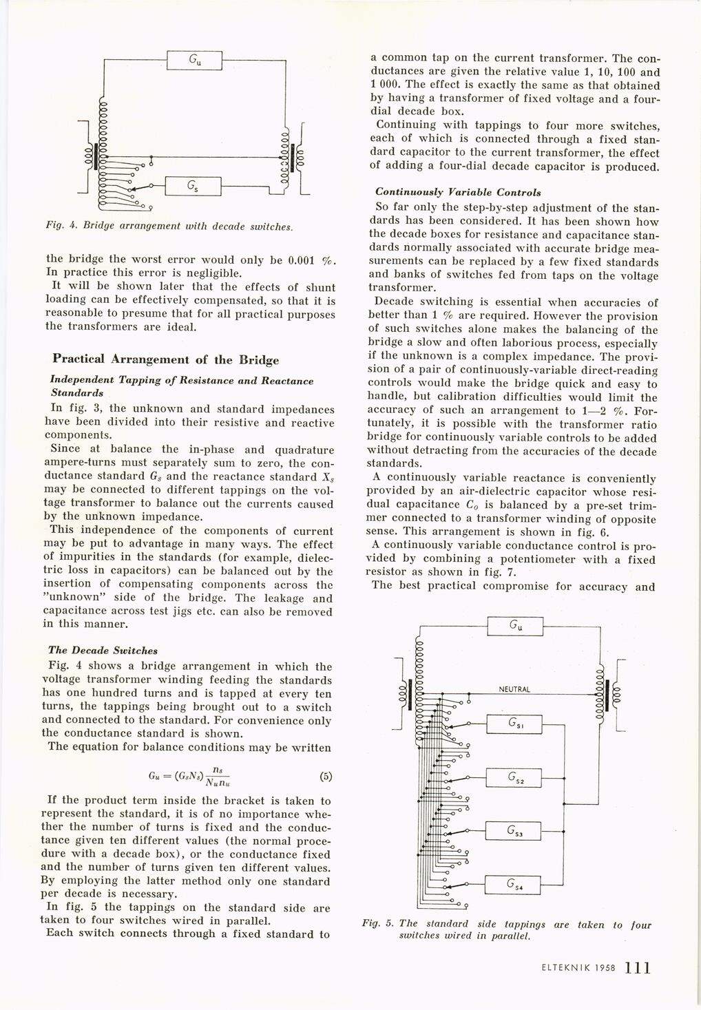
Fig. A. Bridge arrangement with decade switches.
the bridge the worst error would only be 0.001 %.
In practice this error is negligible.
It will be shown later that the effects of shunt
loading can be effectively compensated, so that it is
reasonable to presume that for all practical purposes
the transformers are ideal.
Practical Arrangement of the Bridge
Independent Tapping of Resistance and Reactance
Standards
In fig. 3, the unknown and standard impedances
have been divided into their resistive and reactive
components.
Since at balance the in-phase and quadrature
ampere-turns must separately sum to zero, the
conductance standard Gs and the reactance standard Xs
may be connected to different tappings on the
voltage transformer to balance out the currents caused
by the unknown impedance.
This independence of the components of current
may be put to advantage in many ways. The effect
of impurities in the standards (for example,
dielectric loss in capacitors) can be balanced out by the
insertion of compensating components across the
"unknown" side of the bridge. The leakage and
capacitance across test jigs etc. can also be removed
in this manner.
The Decade Switches
Fig. 4 shows a bridge arrangement in which the
voltage transformer winding feeding the standards
has one hundred turns and is tapped at every ten
turns, the tappings being brought out to a switch
and connected to the standard. For convenience only
the conductance standard is shown.
The equation for balance conditions may be written
n«
Gu = (GsiV«) tt—— (5)
Nunu
If the product term inside the bracket is taken to
represent the standard, it is of no importance
whether the number of turns is fixed and the
conductance given ten different values (the normal
procedure with a decade box), or the conductance fixed
and the number of turns given ten different values.
By employing the latter method only one standard
per decade is necessary.
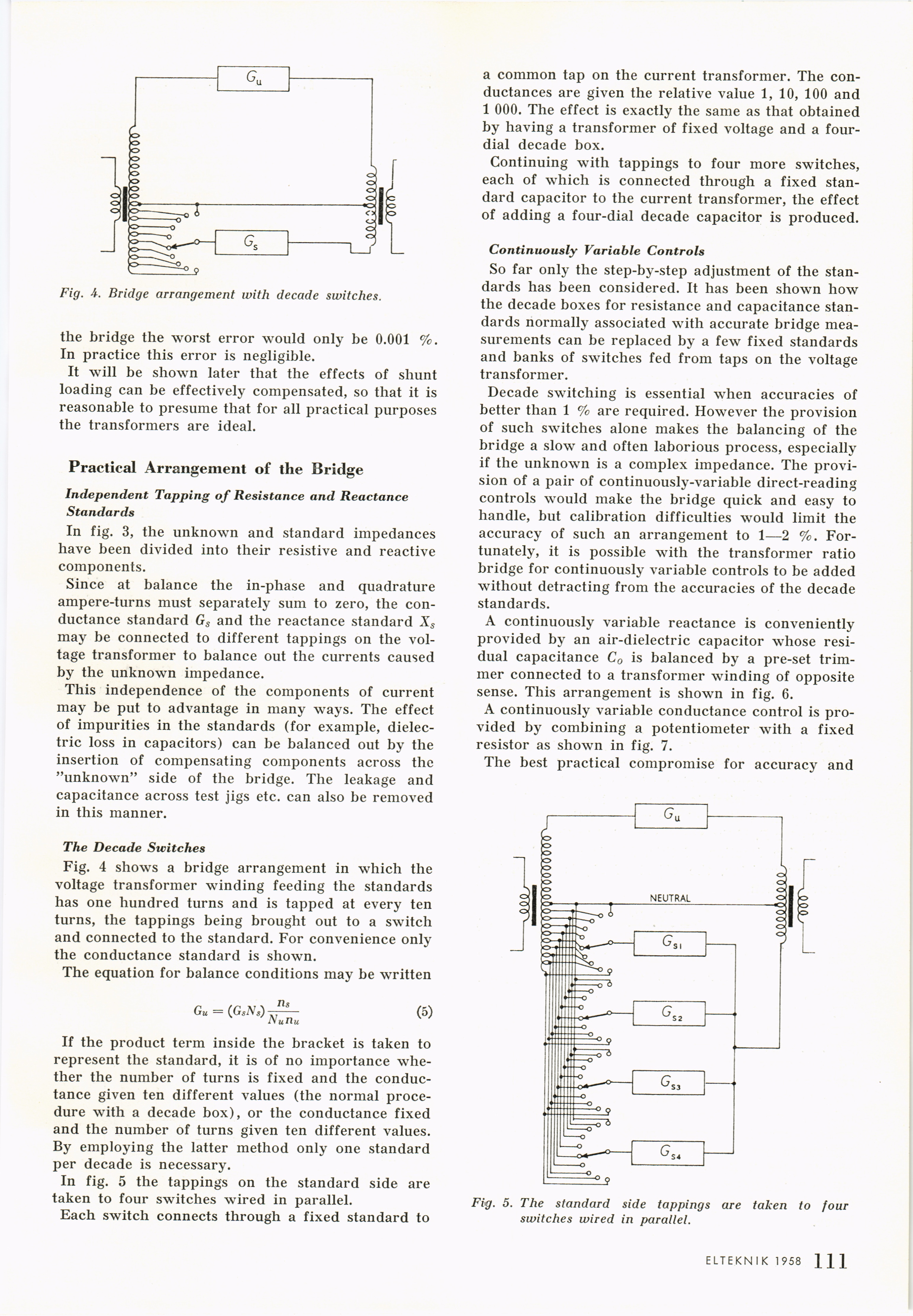
In fig. 5 the tappings on the standard side are
taken to four switches wired in parallel.
Each switch connects through a fixed standard to
a common tap on the current transformer. The
conductances are given the relative value 1, 10, 100 and
1 000. The effect is exactly the same as that obtained
by having a transformer of fixed voltage and a
four-dial decade box.
Continuing with tappings to four more switches,
each of which is connected through a fixed
standard capacitor to the current transformer, the effect
of adding a four-dial decade capacitor is produced.
Continuously Variable Controls
So far only the step-by-step adjustment of the
standards has been considered. It has been shown how
the decade boxes for resistance and capacitance
standards normally associated with accurate bridge
measurements can be replaced by a few fixed standards
and banks of switches fed from taps on the voltage
transformer.
Decade switching is essential when accuracies of
better than 1 % are required. However the provision
of such switches alone makes the balancing of the
bridge a slow and often laborious process, especially
if the unknown is a complex impedance. The
provision of a pair of continuously-variable direct-reading
controls would make the bridge quick and easy to
handle, but calibration difficulties would limit the
accuracy of such an arrangement to 1—2 %.
Fortunately, it is possible with the transformer ratio
bridge for continuously variable controls to be added
without detracting from the accuracies of the decade
standards.
A continuously variable reactance is conveniently
provided by an air-dielectric capacitor whose
residual capacitance C0 is balanced by a pre-set
trimmer connected to a transformer winding of opposite
sense. This arrangement is shown in fig. 6.
A continuously variable conductance control is
provided by combining a potentiometer with a fixed
resistor as shown in fig. 7.
The best practical compromise for accuracy and
Fig. 5. The standard side tappings are taken to four
switches wired in parallel.
ELTEKN I K 1958 ] 47
<< prev. page << föreg. sida << >> nästa sida >> next page >>