
Full resolution (JPEG) - On this page / på denna sida - 1958, H. 9 - The Balancing of Unbalanced Three-Phase Loads, by Sune Rusck
<< prev. page << föreg. sida << >> nästa sida >> next page >>
Below is the raw OCR text
from the above scanned image.
Do you see an error? Proofread the page now!
Här nedan syns maskintolkade texten från faksimilbilden ovan.
Ser du något fel? Korrekturläs sidan nu!
This page has never been proofread. / Denna sida har aldrig korrekturlästs.
P = I Pv = 1 pv + £ (Pv eos 2a, + QV sin 2a,) eos 2at +
1 1 1
+ l(Qv eos 2<xv — Pv sin 2a,)sin 2nt (4)
l
where
Pv = uv iv eos (pv — the active power in phase v
Qv = iiv iv sin (pv — the reactive power in phase v
The condition for the three-phase load to be
balanced was, according to the above, that p should be
constant. In order that this should be the case for
each value of t in equation (4), the two terms
dependent on time must each be equal to zero, which
gives
l(Pv eos 2<x.v + Qv sin 2a,) = 0
l
l(Qv cos2av - Pv sin 2ay) = 0
(5)
By multiplying one of these equations with j and
adding the other, equation (5) can also be written
as
I Sv e~i2x* =l(Pv+ jQv) e~’2ocy = 0
(6)
This is the general balance condition.
In passing, it may be stated that, if n — 3, equation
(6) is satisfied by, inter alia, Sx = S2 = S3, <x2 — <x1 =
= ± 2jt/3 and a3 — a, = q= 2jt/3. This solution
includes the case where the transformer is a
conventional symmetrically loaded three-phase transformer.
If n — 2 and S1 = S2, a2 — ct, = ±jr/2. As is well
known, this case can be achieved in practice with
the aid of a Scott-connected transformer.
Discussion of the balance condition
Let us now assume that 5X = + j Q1 is an
arbitrary single-phase load, which is to be balanced
with the aid of reactive loads j Qv connected to the
other secondary windings. If the voltage across
phase 1 is used as a reference phase, i.e. ax = 0,
equation (6) can then be written as
Pi + jQi + ZjQv e-’201* =0 (7)
2
Without going into greater detail concerning the
practical arrangements for the balancing, a certain
number of interesting general conclusions can be
drawn from equation (7). This contains, as can be
seen, 2 (n — 1) unknowns, namely n—reactive
powers and the same number of phase angles. It is
evident that of these variables 2 (n — 1)—2 =
2 (n — 2) can be selected absolutely arbitrarily,
whereas the other two are determined from
equation (7). From this it follows that it is possible to
balance an arbitrary single-phase load with only one
reactive load provided that its supply voltage can
be given at suitable phase angle, and that if two, or
more, reactive loads are used for balancing, the
phase angles for these voltages can be selected
arbitrarily. The secondary voltages can consequently,
in the latter case, be allowed to form, for example,
a balanced three-phase system.
Another question which is directly answered from
equation (7) is the interesting question from the
economic point of view of whether there is any
minimum value for the necessary reactive load in a
certain case. That this is the fact can be perceived
immediately if equation (7) is plotted graphically.
This has been done in fig. 2, where St has been
plotted in a diagram where the axes have been
graduated in P and Q. In order that equation (7)
may be satisfied, it is obvious that the vectorial sum
of the Qv values of the different secondary phases
turned the angles — 2 <xv must be equal to —Sv,
fig. 2 a. It is plain that the minimum value of 21 Qv |
will be
l\Qr\ = |Sl| = l/P2l + Q21
(8)
This value can be attained when n = 2 or 3, figs 2 b
and c. The phase angles of these voltages will then
be a2 = ji/4 — <pj2 and a3 = 3^/4 — yj2. Any other
arrangement of the number and phase angles of the
secondary voltages than that given in the above case
will yield a higher value of the sum of the reactive
volt-amperes used.
Apart from the optimum case, the circuit to be
used is also of interest from the installation point
of view, where the transformer is of normal
three-phase design, since, in this case, components of
standard design can be used.
Three-phase balancing
We shall commence by investigating the case where
the transformer T is a conventional three-phase
transformer, i.e. a2 = — 2^/3 and a3 = 2^/3. If these
values are inserted in equation (7), we then obtain
q2 = Q, -A
j/3^
Qs = Qi + A
r 3
(9)
Since it is still assumed that the transformer does
not have any losses, the three-phase load on the
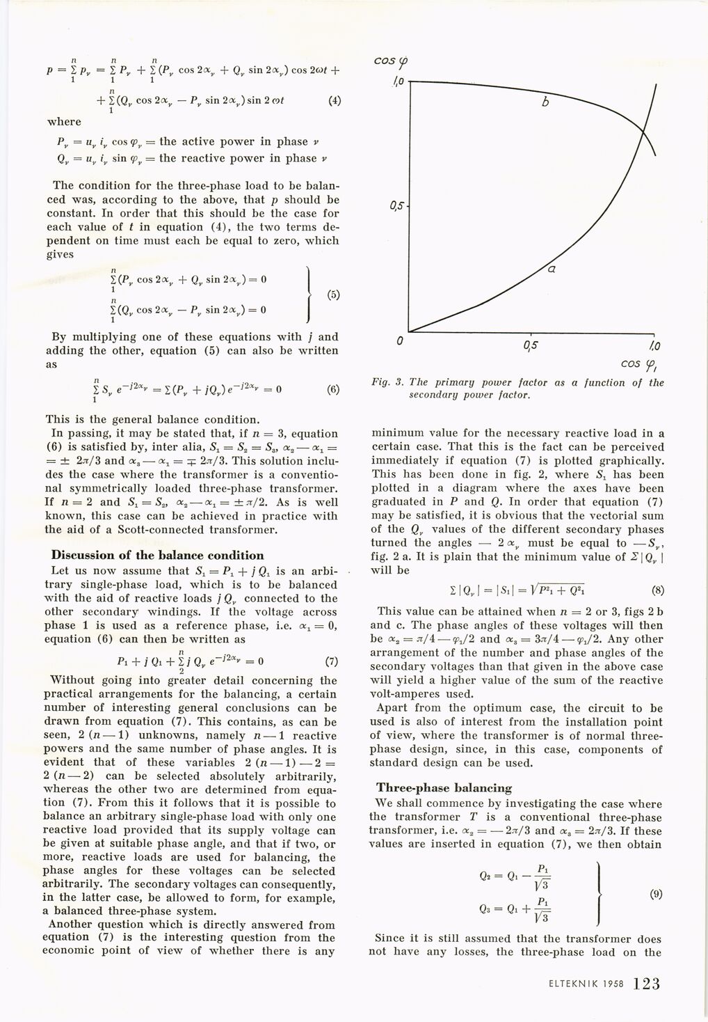
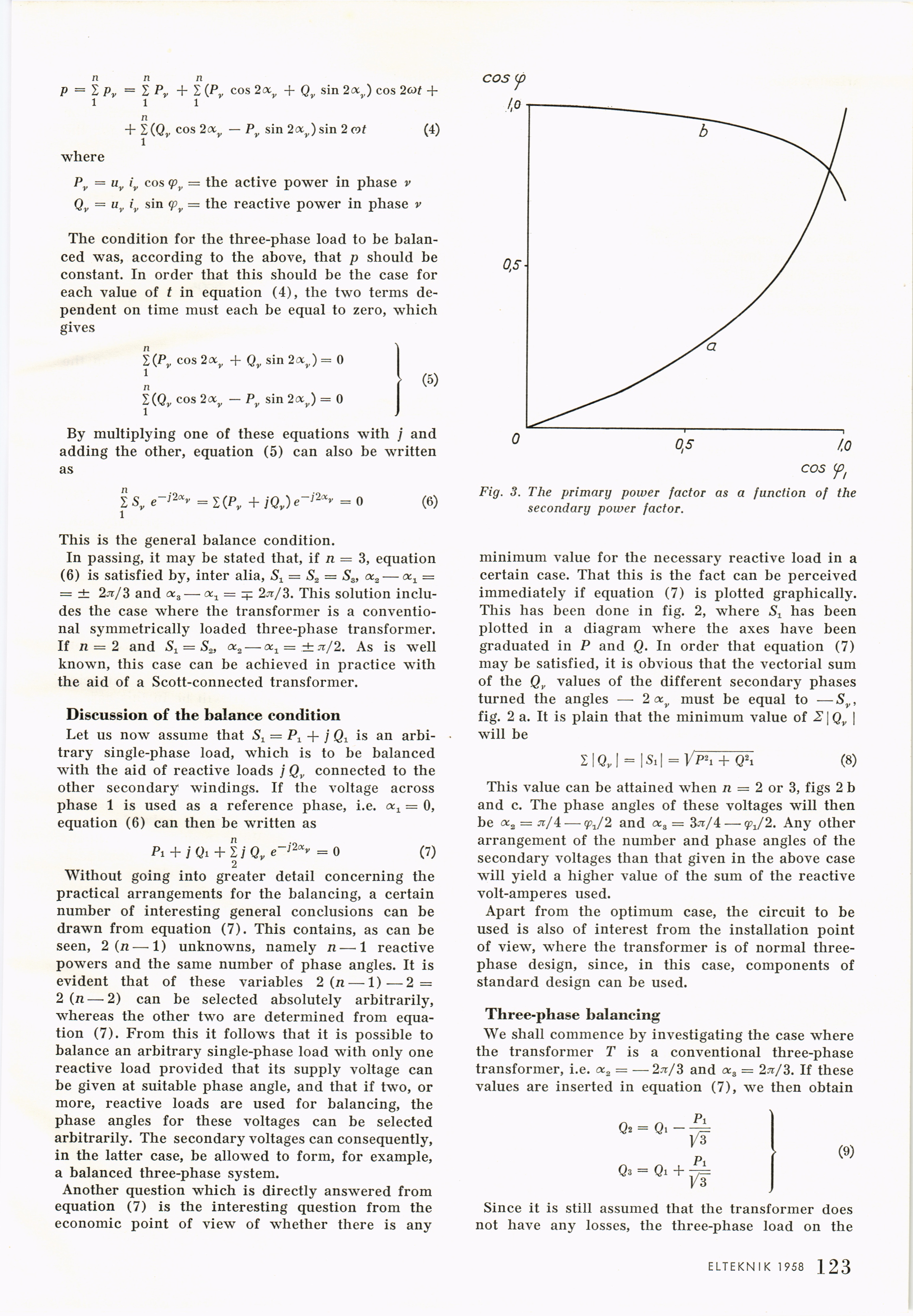
0 0,5 /.O
COS <ft
Fig. 3. The primary power factor as a function of the
secondary power factor.
ELTEKNIK 1958 1 1 9
<< prev. page << föreg. sida << >> nästa sida >> next page >>