
Full resolution (JPEG) - On this page / på denna sida - 1959, H. 4 - Some Aspects on the Design and Use of the Helical Antenna, by göran Svennérus
<< prev. page << föreg. sida << >> nästa sida >> next page >>
Below is the raw OCR text
from the above scanned image.
Do you see an error? Proofread the page now!
Här nedan syns maskintolkade texten från faksimilbilden ovan.
Ser du något fel? Korrekturläs sidan nu!
This page has never been proofread. / Denna sida har aldrig korrekturlästs.
Some Aspects on the Design
and Use of the Helical Antenna
Göran Svennérus, Chief Research Engineer,
Research Institute of National Defence, Stockholm
En axiellt strålande spiralantenn är i allmänhet
försedd med en motvikt i form av ett cirkulärt,
metalliskt jordplan. Inverkan av jordplanets storlek
på antennens strålnings diagram diskuteras. Den
plana motvikten kan med fördel ersättas med en
liten konisk tratt. Mätresultatet, som belyser detta,
presenteras.
Spiralantennens egenskaper som primärstrålare har
experimentellt undersökts. Härvid har
strålnings-fältets amplitud, fas och polarisation studerats. En
spiral omfattande ca två varv erhåller med
användning av trattformad motvikt lämpliga egenskaper
för belysning av rotationssymmetriska
paraboloid-antenner.
A helical antenna radiating in the axial mode is
generally supplied with a counter-poise in the form
of a circular metallic ground plane. The influence
of the ground plane size on the radiation pattern of
the antenna is discussed. The advantages of
replacing the plane counter-poise with a small conical
one are presented. The funnel-shaped counter-poise
is particularly valuable when the helical antenna
is used as a primary source. The properties of the
helical antenna as an illuminator have been
experimentally investigated and the result will be given.
Introduction
The most common type of the helical antenna
radiating in the axial mode consists of a circular
helix provided with a counter-poise in the form of
a circular ground plane. This report presents some
experiences which have been done in connection
with an experimental investigation of such an
antenna. The paper suggests a modification of the
counter-poise especially valuable when the helical
antenna is used as a primary source in a paraboloid
reflector.
It is well known that a circular helix with a
circumference of about one wavelength and a pitch
angle around 15 degrees is suitable for broad band
circularly polarized directive radiation. Maximum
radiation occurs along the axis of the helix within
a frequency band of about ± 25 % of the design
frequency and the impedance of the antenna is
fairly constant within the same frequency limits.
The influence of variations of the helix design (for
instance diameter, pitch angle, number of turns) has
been fully described in several publications,
originally by J. D. Kraus1. Concerning the counter-poise,
however, there has been less discussion.
621.396.677
The influence of ground plane diameter
variation
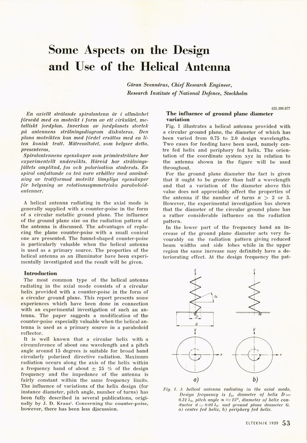
Fig. 1 illustrates a helical antenna provided with
a circular ground plane, the diameter of which has
been varied from 0.75 to 2.0 design wavelengths.
Two cases for feeding have been used, namely
centre fed helix and periphery fed helix. The
orientation of the coordinate system xyz in relation to
the antenna shown in the figure will be used
throughout.
For the ground plane diameter the fact is given
that it ought to be greater than half a wavelength
and that a variation of the diameter above this
value does not appreciably affect the properties of
the antenna if the number of turns n > 2 or 3.
However, the experimental investigation has shown
that the diameter of the circular ground plane has
a rather considerable influence on the radiation
pattern.
In the lower part of the frequency band an
increase of the ground plane diameter acts very
favourably on the radiation pattern giving reduced
beam widths and side lobes while in the upper
region the same increase may definitely have a
deteriorating effect. At the design frequency the pat-
z z
I I
Fig. 1. A helical antenna radiating in the axial mode.
Design frequency is f0, diameter of helix D ■=
0.31l0, pitch angle oc ^ 15°, diameter of helix
conductor d = 0.02 X0 and ground plane diameter G.
a) centre fed helix, b) periphery fed helix.
ELTEKNIK 1959 1 53
<< prev. page << föreg. sida << >> nästa sida >> next page >>