
Full resolution (JPEG) - On this page / på denna sida - 1959, H. 4 - Some Aspects on the Design and Use of the Helical Antenna, by göran Svennérus

<< prev. page << föreg. sida << >> nästa sida >> next page >>
Below is the raw OCR text
from the above scanned image.
Do you see an error? Proofread the page now!
Här nedan syns maskintolkade texten från faksimilbilden ovan.
Ser du något fel? Korrekturläs sidan nu!
This page has never been proofread. / Denna sida har aldrig korrekturlästs.
Fig. 4. An eight-turn helix with a conical counter-poise.
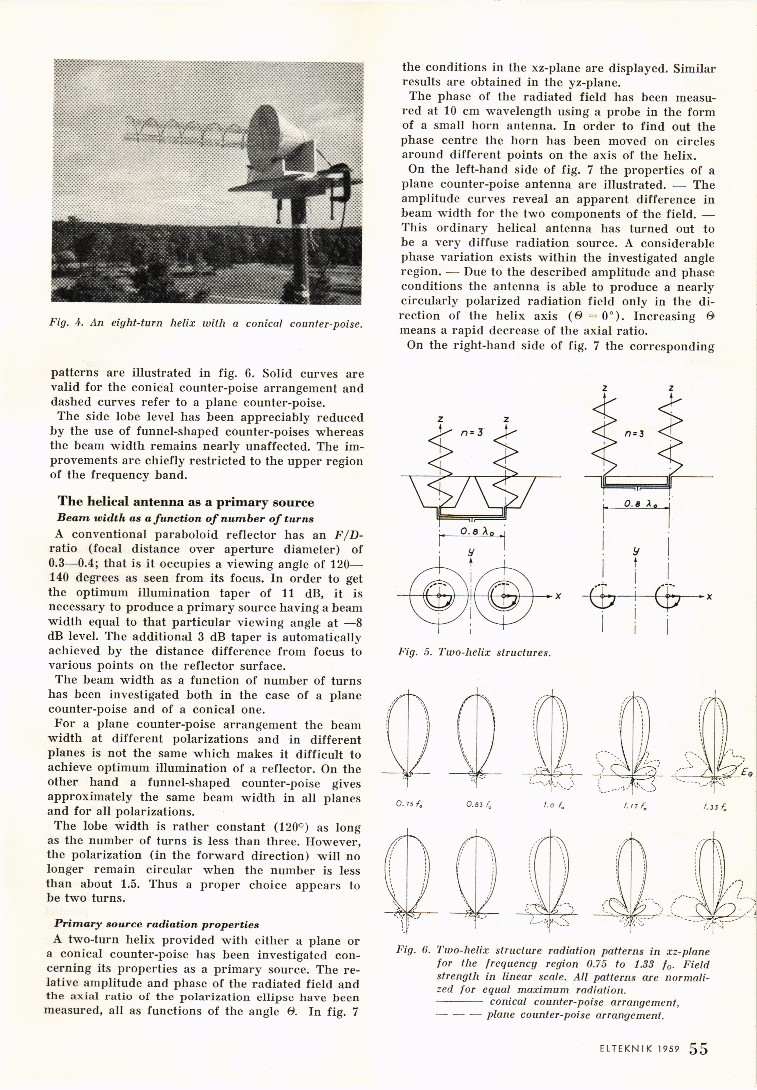
patterns are illustrated in fig. 6. Solid curves are
valid for the conical counter-poise arrangement and
dashed curves refer to a plane counter-poise.
The side lobe level has been appreciably reduced
by the use of funnel-shaped counter-poises whereas
the beam width remains nearly unaffected. The
improvements are chiefly restricted to the upper region
of the frequency band.
The helical antenna as a primary source
Beam width as a function of number of turns
A conventional paraboloid reflector has an
F/D-ratio (focal distance over aperture diameter) of
0.3—0.4; that is it occupies a viewing angle of 120—
140 degrees as seen from its focus. In order to get
the optimum illumination taper of 11 dB, it is
necessary to produce a primary source having a beam
width equal to that particular viewing angle at —8
dB level. The additional 3 dB taper is automatically
achieved by the distance difference from focus to
various points on the reflector surface.
The beam width as a function of number of turns
has been investigated both in the case of a plane
counter-poise and of a conical one.
For a plane counter-poise arrangement the beam
width at different polarizations and in different
planes is not the same which makes it difficult to
achieve optimum illumination of a reflector. On the
other hand a funnel-shaped counter-poise gives
approximately the same beam width in all planes
and for all polarizations.
The lobe width is rather constant (120°) as long
as the number of turns is less than three. However,
the polarization (in the forward direction) will no
longer remain circular when the number is less
than about 1.5. Thus a proper choice appears to
be two turns.
Primary source radiation properties
A two-turn helix provided with either a plane or
a conical counter-poise has been investigated
concerning its properties as a primary source. The
relative amplitude and phase of the radiated field and
the axial ratio of the polarization ellipse have been
measured, all as functions of the angle 6. In fig. 7
the conditions in the xz-plane are displayed. Similar
results are obtained in the yz-plane.
The phase of the radiated field has been
measured at 10 cm wavelength using a probe in the form
of a small horn antenna. In order to find out the
phase centre the horn has been moved on circles
around different points on the axis of the helix.
On the left-hand side of fig. 7 the properties of a
plane counter-poise antenna are illustrated. — The
amplitude curves reveal an apparent difference in
beam width for the two components of the field. —
This ordinary helical antenna has turned out to
be a very diffuse radiation source. A considerable
phase variation exists within the investigated angle
region. — Due to the described amplitude and phase
conditions the antenna is able to produce a nearly
circularly polarized radiation field only in the
direction of the helix axis (Ö = 0°). Increasing ®
means a rapid decrease of the axial ratio.
On the right-hand side of fig. 7 the corresponding
Fig. 6. Two-helix structure radiation patterns in xz-plane
for the frequency region 0.75 to 1.33 f0. Field
strength in linear scale. All patterns are
normalized for equal maximum radiation.
- conical counter-poise arrangement,
–-plane counter-poise arrangement.
Fig. 5. Two-helix structures.
ELTEKNIK 1959 1 55
<< prev. page << föreg. sida << >> nästa sida >> next page >>