
Full resolution (JPEG) - On this page / på denna sida - Back-Scattering Cross Section of Reactively Loaded Cylindrical Antennas, by Bengt-Olof Ås and Hans J. Schmitt

<< prev. page << föreg. sida << >> nästa sida >> next page >>
Below is the raw OCR text
from the above scanned image.
Do you see an error? Proofread the page now!
Här nedan syns maskintolkade texten från faksimilbilden ovan.
Ser du något fel? Korrekturläs sidan nu!
This page has never been proofread. / Denna sida har aldrig korrekturlästs.
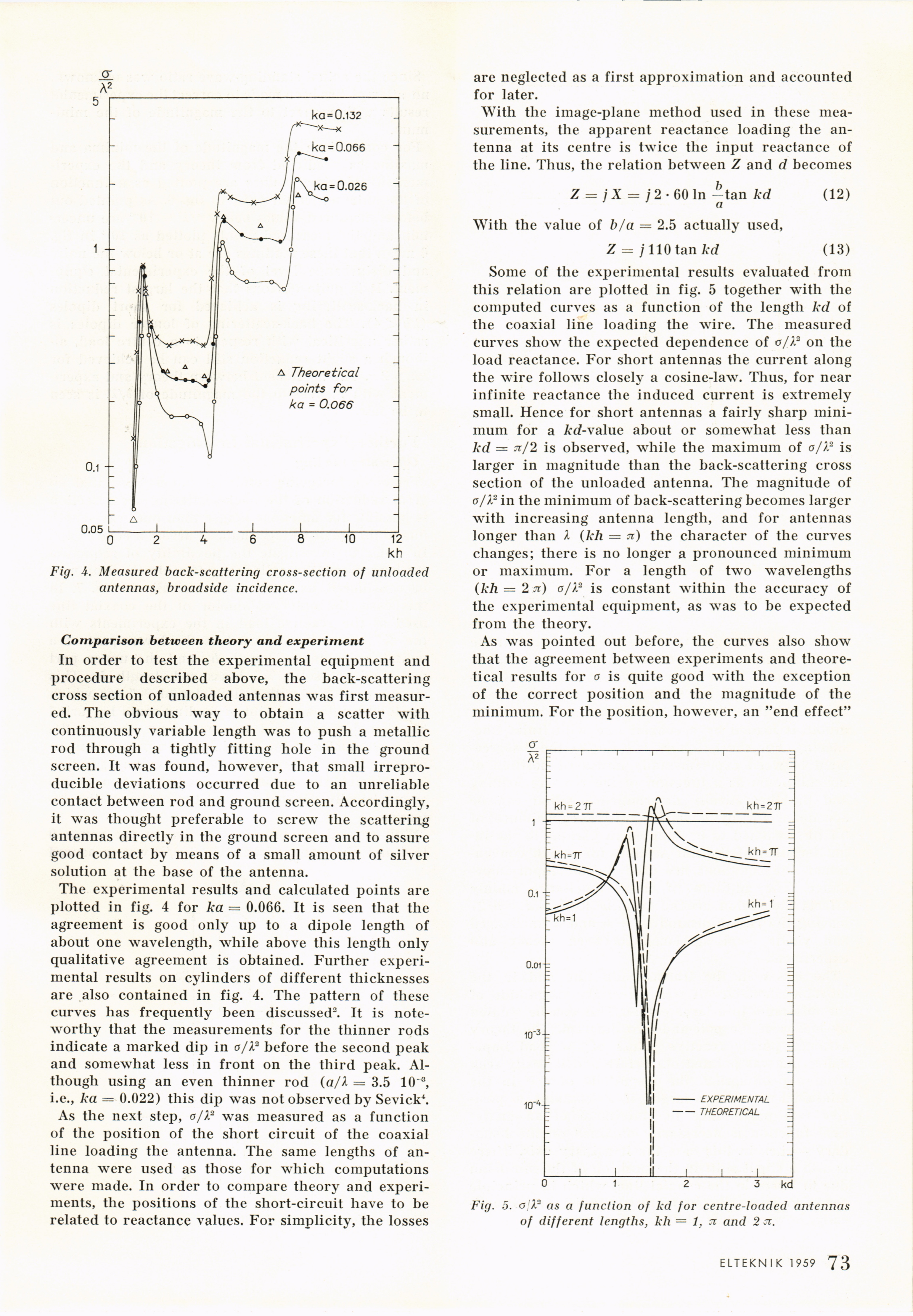
Fig. 4. Measured back-scattering cross-section of unloaded
antennas, broadside incidence.
Comparison between theory and experiment
In order to test the experimental equipment and
procedure described above, the back-scattering
cross section of unloaded antennas was first
measured. The obvious way to obtain a scatter with
continuously variable length was to push a metallic
rod through a tightly fitting hole in the ground
screen. It was found, however, that small
irrepro-ducible deviations occurred due to an unreliable
contact between rod and ground screen. Accordingly,
it was thought preferable to screw the scattering
antennas directly in the ground screen and to assure
good contact by means of a small amount of silver
solution at the base of the antenna.
The experimental results and calculated points are
plotted in fig. 4 for ka = 0.066. It is seen that the
agreement is good only up to a dipole length of
about one wavelength, while above this length only
qualitative agreement is obtained. Further
experimental results on cylinders of different thicknesses
are also contained in fig. 4. The pattern of these
curves has frequently been discussed2. It is
noteworthy that the measurements for the thinner rods
indicate a marked dip in a/X2 before the second peak
and somewhat less in front on the third peak.
Although using an even thinner rod (a/X = 3.5 10~3,
i.e., ka = 0.022) this dip was not observed by Sevick4.
As the next step, a/X2 was measured as a function
of the position of the short circuit of the coaxial
line loading the antenna. The same lengths of
antenna were used as those for which computations
were made. In order to compare theory and
experiments, the positions of the short-circuit have to be
related to reactance values. For simplicity, the losses
are neglected as a first approximation and accounted
for later.
With the image-plane method used in these
measurements, the apparent reactance loading the
antenna at its centre is twice the input reactance of
the line. Thus, the relation between Z and d becomes
Z = / X = / 2 • 60 In —tan kd (12)
a
With the value of b/a = 2.5 actually used,
Z = j 110 tan kd (13)
Some of the experimental results evaluated from
this relation are plotted in fig. 5 together with the
computed curves as a function of the length kd of
the coaxial line loading the wire. The measured
curves show the expected dependence of a/X2 on the
load reactance. For short antennas the current along
the wire follows closely a cosine-law. Thus, for near
infinite reactance the induced current is extremely
small. Hence for short antennas a fairly sharp
minimum for a A-d-value about or somewhat less than
kd — n/2 is observed, while the maximum of o/X2 is
larger in magnitude than the back-scattering cross
section of the unloaded antenna. The magnitude of
a/X2 in the minimum of back-scattering becomes larger
with increasing antenna length, and for antennas
longer than X (kh = .t) the character of the curves
changes; there is no longer a pronounced minimum
or maximum. For a length of two wavelengths
(kh = 2 n) o/X2 is constant within the accuracy of
the experimental equipment, as was to be expected
from the theory.
As was pointed out before, the curves also show
that the agreement between experiments and
theoretical results for a is quite good with the exception
of the correct position and the magnitude of the
minimum. For the position, however, an "end effect"
Fig. 5. o X2 as a function of kd for centre-loaded antennas
of different lengths, kh = 1, n and 2 ci.
ELTEKNIK 1959 1 73
<< prev. page << föreg. sida << >> nästa sida >> next page >>