
Full resolution (JPEG) - On this page / på denna sida - On the Temperature Margins of a Transistor-Driven Coincident Current Ferrite Core Memory, by Jan-Rustan Törnquist
<< prev. page << föreg. sida << >> nästa sida >> next page >>
Below is the raw OCR text
from the above scanned image.
Do you see an error? Proofread the page now!
Här nedan syns maskintolkade texten från faksimilbilden ovan.
Ser du något fel? Korrekturläs sidan nu!
This page has never been proofread. / Denna sida har aldrig korrekturlästs.
Thus dvt, affecting Ix can be written as
dvu = 1> • iiVx
(7)
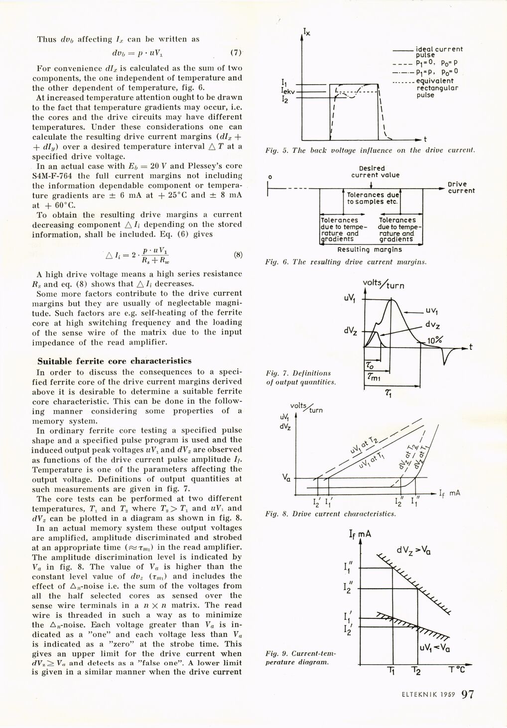
For convenience dlx is calculated as the sum of two
components, the one independent of temperature and
the other dependent of temperature, fig. 6.
At increased temperature attention ought to be drawn
to the fact that temperature gradients may occur, i.e.
the cores and the drive circuits may have different
temperatures. Under these considerations one can
calculate the resulting drive current margins (dlx -f
+ dly) over a desired temperature interval A T at a
specified drive voltage.
In an actual case with Eo = 20 V and Plessey’s core
S4M-F-764 the full current margins not including
the information dependable component or
temperature gradients are ± 6 mA at + 25° C and ± 8 mA
at + 60 °C.
To obtain the resulting drive margins a current
decreasing component A h depending on the stored
information, shall be included. Eq. (6) gives
A I i = 2
puV i
a, + K»
(8)
A high drive voltage means a high series resistance
R,s and eq. (8) shows that A h decreases.
Some more factors contribute to the drive current
margins but they are usually of neglectable
magnitude. Such factors are e.g. self-heating of the ferrite
core at high switching frequency and the loading
of the sense wire of the matrix due to the input
impedance of the read amplifier.
Suitable ferrite core characteristics
In order to discuss the consequences to a
specified ferrite core of the drive current margins derived
above it is desirable to determine a suitable ferrite
core characteristic. This can be done in the
following manner considering some properties of a
memory system.
In ordinary ferrite core testing a specified pulse
shape and a specified pulse program is used and the
induced output peak voltages uVt and dVz are observed
as functions of the drive current pulse amplitude If.
Temperature is one of the parameters affecting the
output voltage. Definitions of output quantities at
such measurements are given in fig. 7.
The core tests can be performed at two different
temperatures, T1 and T„ where T.2 > 7\ and uVi and
dVz can be plotted in a diagram as shown in fig. 8.
In an actual memory system these output voltages
are amplified, amplitude discriminated and strobed
at an appropriate time in the read amplifier.
The amplitude discrimination level is indicated by
Va in fig. 8. The value of Va is higher than the
constant level value of dvz (tmi) and includes the
effect of A„-noise i.e. the sum of the voltages from
all the half selected cores as sensed over the
sense wire terminals in a n X « matrix. The read
wire is threaded in such a way as to minimize
the A »-noise. Each voltage greater than Va is
indicated as a "one" and each voltage less than Va
is indicated as a "zero" at the strobe time. This
gives an upper limit for the drive current when
dVz^Va and detects as a "false one". A lower limit
is given in a similar manner when the drive current
Fig. 5. The back voltage influence on the drive current.
Fig. 0. The resulting drive current margins.
Fig. 7. Definitions
of output quantities.
Fig. 8. Drive current characteristics
Fig. 9.
Current-temperature diagram.
ELTEKNIK 195? 97
<< prev. page << föreg. sida << >> nästa sida >> next page >>