
Full resolution (JPEG) - On this page / på denna sida - A Ferrite Core Memory for Storage of Teleprinter Signals, by Rolf von Campenhausen
<< prev. page << föreg. sida << >> nästa sida >> next page >>
Below is the raw OCR text
from the above scanned image.
Do you see an error? Proofread the page now!
Här nedan syns maskintolkade texten från faksimilbilden ovan.
Ser du något fel? Korrekturläs sidan nu!
This page has never been proofread. / Denna sida har aldrig korrekturlästs.
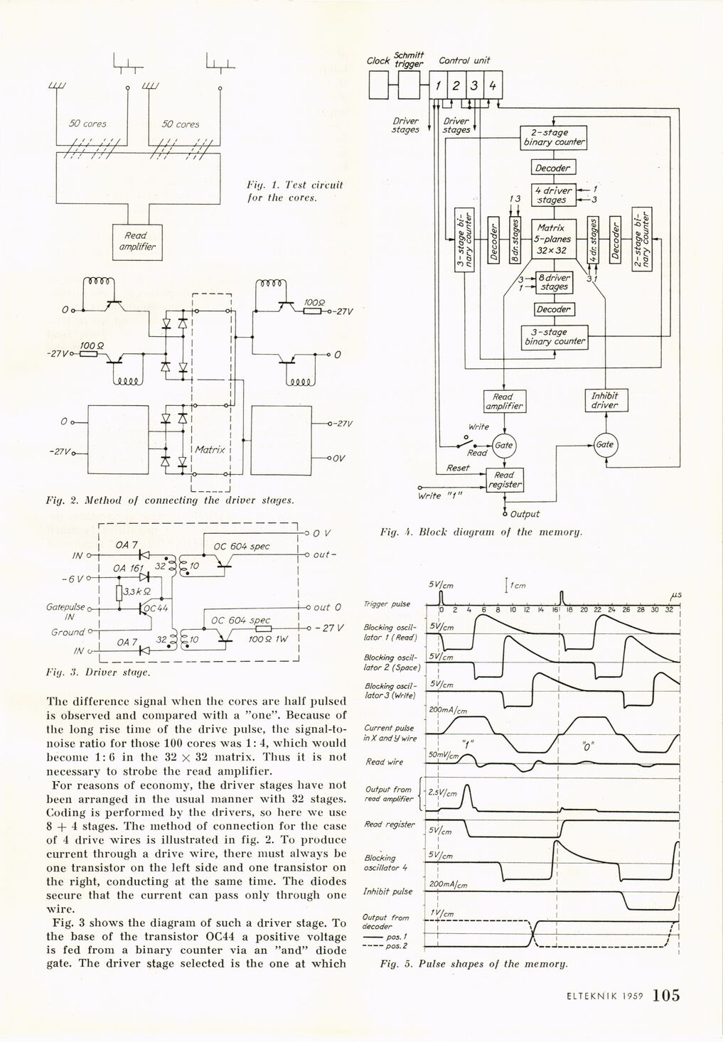
Fig. 1. Test circuit
for the cores.
I______I
Fig. 2. Method of connecting the driver stages.
Fig. 3. Driver stage.
The difference signal when the cores are half pulsed
is observed and compared with a "one". Because of
the long rise time of the drive pulse, the
signal-to-noise ratio for those 100 cores was 1: 4, which would
become 1:6 in the 32 x 32 matrix. Thus it is not
necessary to strobe the read amplifier.
For reasons of economy, the driver stages have not
been arranged in the usual manner with 32 stages.
Coding is performed by the drivers, so here we use
8 + 4 stages. The method of connection for the case
of 4 drive wires is illustrated in fig. 2. To produce
current through a drive wire, there must always be
one transistor on the left side and one transistor on
the right, conducting at the same time. The diodes
secure that the current can pass only through one
wire.
Fig. 3 shows the diagram of such a driver stage. To
the base of the transistor OC44 a positive voltage
is fed from a binary counter via an "and" diode
gate. The driver stage selected is the one at which
Fig. A. Block diagram of the memory.
Fig. 5. Pulse shapes of the memory.
ELTEKNIK 1959 1 105
<< prev. page << föreg. sida << >> nästa sida >> next page >>