
Full resolution (JPEG) - On this page / på denna sida - 1958, H. 6 - Up-to-date Criteria in the Construction of Equipment for High Voltage Power Systems According to the Experience of the 400 kV System in Sweden, by Gunnar Jancke
<< prev. page << föreg. sida << >> nästa sida >> next page >>
Below is the raw OCR text
from the above scanned image.
Do you see an error? Proofread the page now!
Här nedan syns maskintolkade texten från faksimilbilden ovan.
Ser du något fel? Korrekturläs sidan nu!
This page has never been proofread. / Denna sida har aldrig korrekturlästs.
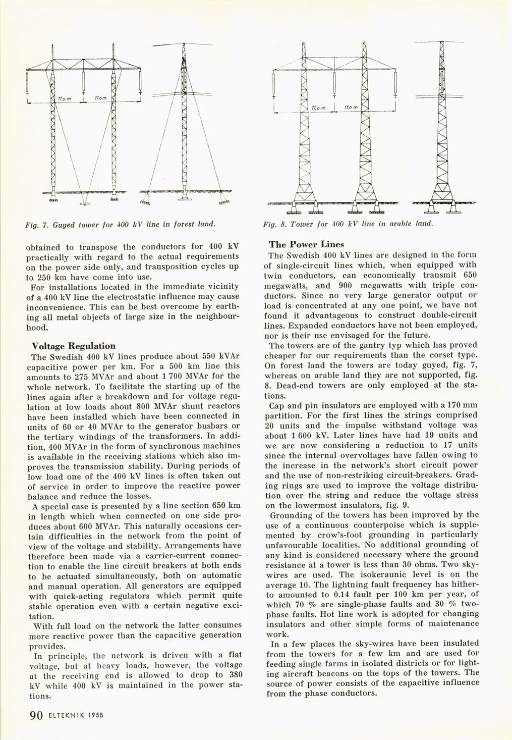
Fig. 7. Guyed tower for 400 kV line in forest land.
obtained to transpose the conductors for 400 kV
practically with regard to the actual requirements
on the power side only, and transposition cycles up
to 250 km have come into use.
For installations located in the immediate vicinity
of a 400 kV line the electrostatic influence may cause
inconvenience. This can be best overcome by
earthing all metal objects of large size in the
neighbourhood.
Voltage Regulation
The Swedish 400 kV lines produce about 550 kVAr
capacitive power per km. For a 500 km line this
amounts to 275 MVAr and about 1 700 MVAr for the
whole network. To facilitate the starting up of the
lines again after a breakdown and for voltage
regulation at low loads about 800 MVAr shunt reactors
have been installed which have been connected in
units of 60 or 40 MVAr to the generator busbars or
the tertiary windings of the transformers. In
addition, 400 MVAr in the form of synchronous machines
is available in the receiving stations which also
improves the transmission stability. During periods of
low load one of the 400 kV lines is often taken out
of service in order to improve the reactive power
balance and reduce the losses.
A special case is presented by a line section 650 km
in length which when connected on one side
produces about 600 MVAr. This naturally occasions
certain difficulties in the network from the point of
view of the voltage and stability. Arrangements have
therefore been made via a carrier-current
connection to enable the line circuit breakers at both ends
to be actuated simultaneously, both on automatic
and manual operation. All generators are equipped
with quick-acting regulators which permit quite
stable operation even with a certain negative
excitation.
With full load on the network the latter consumes
more reactive power than the capacitive generation
provides.
In principle, the network is driven with a flat
voltage, but at heavy loads, however, the voltage
at the receiving end is allowed to drop to 380
kV while 400 kV is maintained in the power
stations.
Fig. 8. Tower for 400 kV line in arable land.
The Power Lines
The Swedish 400 kV lines are designed in the form
of single-circuit lines which, when equipped with
twin conductors, can economically transmit 650
megawatts, and 900 megawatts with triple
conductors. Since no very large generator output or
load is concentrated at any one point, we have not
found it advantageous to construct double-circuit
lines/Expanded conductors have not been employed,
nor is their use envisaged for the future.
The towers are of the gantry typ which has proved
cheaper for our requirements than the corset type.
On forest land the towers are today guyed, fig. 7,
whereas on arable land they are not supported, fig.
8. Dead-end towers are only employed at the
stations.
Cap and pin insulators are employed with a 170 mm
partition. For the first lines the strings comprised
20 units and the impulse withstand voltage was
about 1 600 kV. Later lines have had 19 units and
we are now considering a reduction to 17 units
since the internal overvoltages have fallen owing to
the increase in the network’s short circuit power
and the use of non-restriking circuit-breakers.
Grading rings are used to improve the voltage
distribution over the string and reduce the voltage stress
on the lowermost insulators, fig. 9.
Grounding of the towers has been improved by the
use of a continuous counterpoise which is
supplemented by crow’s-foot grounding in particularly
unfavourable localities. No additional grounding of
any kind is considered necessary where the ground
resistance at a tower is less than 30 ohms. Two
sky-wires are used. The isokeraunic level is on the
average 10. The lightning fault frequency has
hitherto amounted to 0.14 fault per 100 km per year, of
which 70 % are single-phase faults and 30 %
two-phase faults. Hot line work is adopted for changing
insulators and other simple forms of maintenance
work.
In a few places the sky-wires have been insulated
from the towers for a few km and are used for
feeding single farms in isolated districts or for
lighting aircraft beacons on the tops of the towers. The
source of power consists of the capacitive influence
from the phase conductors.
1 90 ELTEKN I K 1958
<< prev. page << föreg. sida << >> nästa sida >> next page >>