
Full resolution (JPEG) - On this page / på denna sida - 1958, H. 7 - The Quarter-Wave Dipole, by Bengt Josephson
<< prev. page << föreg. sida << >> nästa sida >> next page >>
Below is the raw OCR text
from the above scanned image.
Do you see an error? Proofread the page now!
Här nedan syns maskintolkade texten från faksimilbilden ovan.
Ser du något fel? Korrekturläs sidan nu!
This page has never been proofread. / Denna sida har aldrig korrekturlästs.
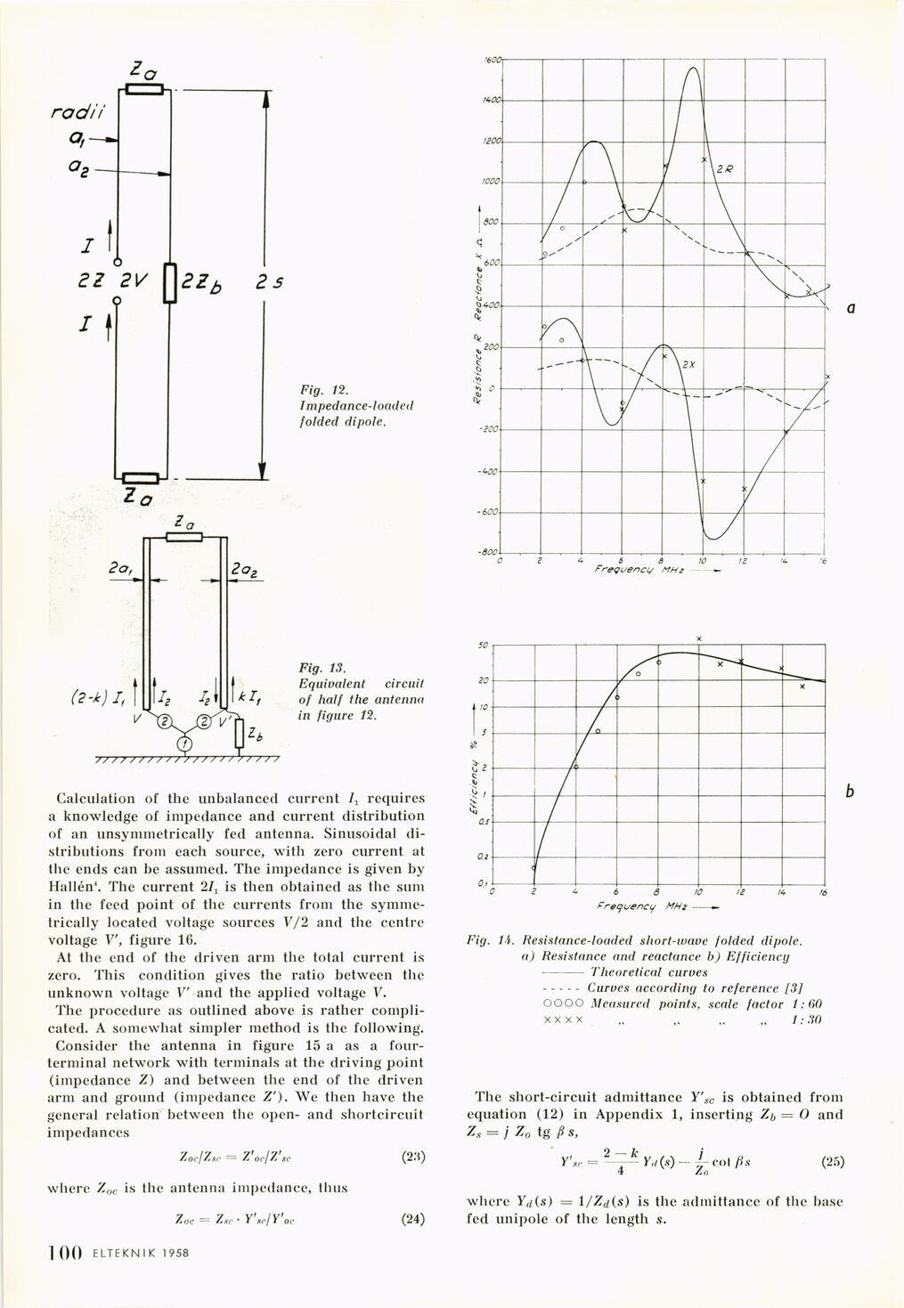
Fig. 12.
Impedance-loaded
folded dipole.
Fig. 13.
Equivalent circuit
of half the antenna
in figure 12.
Calculation of the unbalanced current It requires
a knowledge of impedance and current distribution
of an unsymmetrically fed antenna. Sinusoidal
distributions from each source, with zero current at
the ends can be assumed. The impedance is given by
Hallén4. The current 2Ix is then obtained as the sum
in the feed point of the currents from the
symmetrically located voltage sources V/2 and the centre
voltage V, figure 16.
At the end of the driven arm the total current is
zero. This condition gives the ratio between the
unknown voltage V’ and the applied voltage V.
The procedure as outlined above is rather
complicated. A somewhat simpler method is the following.
Consider the antenna in figure 15 a as a
four-terminal network with terminals at the driving" point
(impedance Z) and between the end of the driven
arm and ground (impedance Z’). We then have the
general relation between the open- and shortcircuit
impedances
Zor/Zsc = Z’oc/Z’sc
where Zoc is the antenna impedance, thus
Zoc — Zxc • Y’,tr/Y or (24)
Fig. 71. Resistance-loaded short-wave folded dipole.
a) Resistance and reactance b) Efficiency
- Theoretical curves
––- Curves according to reference [3]
OOOO Measured points, scale factor 1:60
x x x x „ ,. 1:30
The short-circuit admittance Y’sc is obtained from
equation (12) in Appendix 1, inserting Z^ = Ö and
= j Z0 tg ß s,
Y’XI
2~-^Yfl(s)~ i col fi,
+ /.o
(25)
where Yrf(s) = 1 /Zci\s) is the admittance of the base
fed unipole of the length s.
1 00 ELTEKN I K 1958
<< prev. page << föreg. sida << >> nästa sida >> next page >>