
Full resolution (JPEG) - On this page / på denna sida - Field Measurements of Lightning Currents, by Nils Hyltén-Cavallius and Åke Strömberg
<< prev. page << föreg. sida << >> nästa sida >> next page >>
Below is the raw OCR text
from the above scanned image.
Do you see an error? Proofread the page now!
Här nedan syns maskintolkade texten från faksimilbilden ovan.
Ser du något fel? Korrekturläs sidan nu!
This page has never been proofread. / Denna sida har aldrig korrekturlästs.
duty for the authors to express the gratitude of
Asea and IYA:s Lightning Committee No. 3 to all
those who have assisted during the measurements.
The inspection and the evaluation of the recorded
data was made by Asea.
The measuring equipment
Fig. 1 shows a measuring device mounted on the
lightning rod of a chimney. The "nesting-box"
contains the device for the measurement of current
steepness while the wooden frame is a holder for
especially constructed magnetic links which allow
the measurement of current amplitudes in the
conventional way but also give some indication of its
duration.
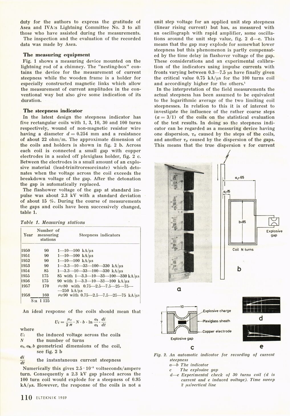
The steepness indicator
In the latest design the steepness indicator has
five rectangular coils with 1, 3, 10, 30 and 100 turns
respectively, wound of non-magnetic resistor wire
having a diameter d = 0.254 mm and a resistance
of about 22 ohm/m. The approximate dimension of
the coils and holders is shown in fig. 2 b. Across
each coil is connected a small gap with copper
electrodes in a sealed off plexiglass holder, fig. 2 c.
Between the electrodes is a small amount of an
explosive material (lead-trinitroresorcinate) which
detonates when the voltage across the coil exceeds the
breakdown voltage of the gap. After the detonation
the gap is automatically replaced.
The flashower voltage of the gap at standard
impulse was about 2.3 kV with a standard deviation
of about 15 %. During the course of measurements
the gaps and coils have been successively changed,
table 1.
Table 1. Measuring stations
Year Number measurir stations of ig Steepness indicators
1950 90 1—10—100 kA/fxs
1951 90 1—10—100 kA/ns
1952 90 1—10—100 kA/fis
1953 90 1—3.3—10—33—100—330 kA/^s
1954 85 1—3.3—10—33—100—330 kA/^is
1955 175 85 with 1—3.3—10—33—100—330 kA/^s
1956 175 90 with 1—3.3—10—33—100 kA/jis
1957 170 ^80 with 0.75—2.5—7.5—25—75—
—250 kA/ps
1958 160 ^90 with 0.75—2.5—7.5—25—75 kA/ps
S:a 1 125
An ideal response of the coils should mean that
2 71
, ö2 di
In–-—
ai dt
where
Ui the induced voltage across the coils
N the number of turns
ai, a», b geometrical dimensions of the coil,
see fig. 2 b
^ the instantaneous current steepness
Numerically this gives 2.5 • 10~8 voltseconds/ampere
turn. Consequently a 2.3 kV gap placed across the
100 turn coil would explode for a steepness of 0.95
kA/ps. However, the response of the coils is not a
unit step voltage for an applied unit step steepness
(linear rising current) but has, as measured with
an oscillograph with rapid amplifier, some
oscillations around the unit step value, fig. 2 d—e. This
means that the gap may explode for somewhat lower
steepness but this phenomenon is partly
compensated by the time delay in flashover voltage of the gap.
These considerations and an experimental
calibration of the indicators using impulse currents with
fronts varying between 0.3—7.5 us have finally given
the critical value 0.75 kA/ps for the 100 turns coil
and accordingly higher for the others.1
In the interpretation of the field measurements the
actual steepness has been assumed to be equivalent
to the logarithmic average of the two limiting coil
steepnesses. In relation to this it is of interest to
investigate the influence of the rather coarse steps
(a = 3/1) of the coils on the statistical evaluation
of the test results. In doing so the steepness
indicator can be regarded as a measuring device having
one dispersion, ra caused by the steps of the coils,
and another rg caused by the dispersion of the gaps.
This means that the true dispersion t for current
Fig. 2. An automatic indicator for recording of current
steepness
a—b The indicator
c The explosive gap
d—e Experimental check of 30 turns coil (d is
current and e induced voltage). Time sweep
2 [xs!vertical line
ELTEKN I K 1959 ] 3 1
<< prev. page << föreg. sida << >> nästa sida >> next page >>