
Full resolution (JPEG) - On this page / på denna sida - The Öresund Power Cable of 1958, by Anders Bergman, Wilhelm Carlshem and Gottschalk von Geijer
<< prev. page << föreg. sida << >> nästa sida >> next page >>
Below is the raw OCR text
from the above scanned image.
Do you see an error? Proofread the page now!
Här nedan syns maskintolkade texten från faksimilbilden ovan.
Ser du något fel? Korrekturläs sidan nu!
This page has never been proofread. / Denna sida har aldrig korrekturlästs.
extremely severe winters, however, the straits may
he filled by pack-ice. As a protection the cable is
provided with a very effective shore protection.
To facilitate the raising of the cable if repairs
should become necessary at some future date, it has
been laid with a certain excess length or slack. An
ample slack also is of importance with an uneven
bottom profile as it allows the cable to lie close
against the bottom. The cable-laying ship was
obliged to sail over a zig-zag course in order to pay out
the required excess length of cable. This presented
a somewhat difficult problem in navigation on
account of the strong current flowing in the straits.
Choice of a cable-laying ship
Cable-laying ships are usually employed for laying
submarine cables. These vessels are constructed with
special tanks in which the cable is stored in coils.
From the tanks the cable is paid out over a capstan
from the stern of the vessel. In this method of laying
the cable is subjected to torsion, and as the space
in the tanks is limited the cable coils will necessarily
be somewhat small. Since, moreover, the bottom in
this case is very shallow for some distance from
the shore and cable-laying ships have a fairly deep
draft the conventional method of laying was found
unsuitable here also. A floating drum designed for
laying power cables was produced by the Nordiske
Kabel- og Traadfabriker at the beginning of the
1950s. The owners kindly placed this floating drum
at the disposal of Sieverts Kabelverk, which firm
was entirely responsible for the actual laying. The
appearance of the drum is illustrated in fig. 4. The
carrying capacity of the drum is approximately 250
tons of cable and the draft at this load is about
5.2 m. The drum has a diameter of 6 metres.
Telecommunication system during laying
When laying out the cable a rapid system of
intercommunication must be available, primarily,
between the floating drum and the tugboat and also
between the respective shores and the tugboat. A
station mounted in a motor vehicle was employed
on the Swedish shore, whereas portable radio sets
were used on the Danish shore and also on the
tugboat and floating drum. The radio system
operated in the 36 and 75 MHz bands with simplex
telephony.
Navigation
The Danish Decca chain was used as an aid to
navigation in laying the cable. The Decca receiver
on board the main tugboat was equipped with a
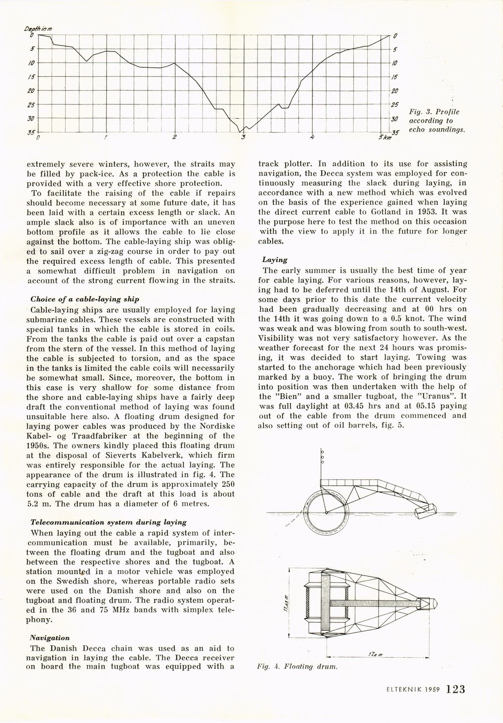
Fig. 3. Profile
according to
echo soundings.
track plotter. In addition to its use for assisting
navigation, the Decca system was employed for
continuously measuring the slack during laying, in
accordance with a new method which was evolved
on the basis of the experience gained when laying
the direct current cable to Gotland in 1953. It was
the purpose here to test the method on this occasion
with the view to apply it in the future for longer
cables.
Laying
The early summer is usually the best time of year
for cable laying. For various reasons, however,
laying had to be deferred until the 14th of August. For
some days prior to this date the current velocity
had been gradually decreasing and at 00 hrs on
the 14th it was going down to a 0.5 knot. The wind
was weak and was blowing from south to south-west.
Visibility was not very satisfactory however. As the
weather forecast for the next 24 hours was
promising, it was decided to start laying. Towing was
started to the anchorage which had been previously
marked by a buoy. The work of bringing the drum
into position was then undertaken with the help of
the "Bien" and a smaller tugboat, the "Uranus". It
was full daylight at 03.45 hrs and at 05.15 paying
out of the cable from the drum commenced and
also setting out of oil barrels, fig. 5.
Fig. A. Floating drum.
ELTEKNIK 1959 1 123
<< prev. page << föreg. sida << >> nästa sida >> next page >>