
Full resolution (JPEG) - On this page / på denna sida - Strength of Materials - Deflection in beams when loaded transversely - To calculate deflection in beams under different modes of support and load
<< prev. page << föreg. sida << >> nästa sida >> next page >>
Below is the raw OCR text
from the above scanned image.
Do you see an error? Proofread the page now!
Här nedan syns maskintolkade texten från faksimilbilden ovan.
Ser du något fel? Korrekturläs sidan nu!
This page has never been proofread. / Denna sida har aldrig korrekturlästs.
s =
Mkl-.M;i’H OF MATERIALS. 26
1
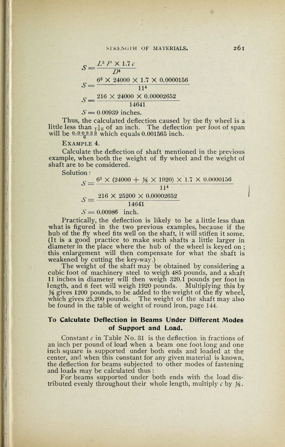
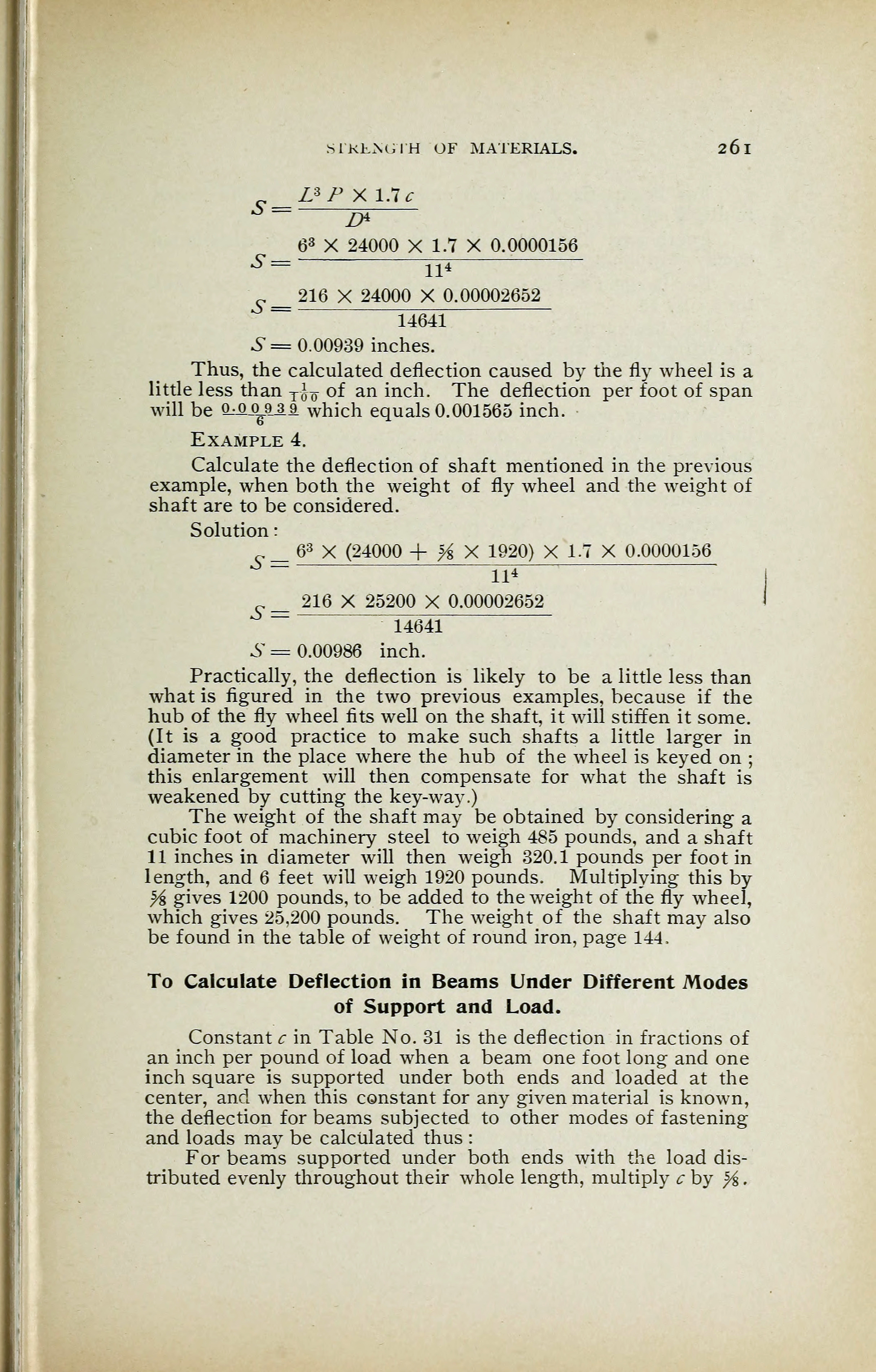
UP X 1.7*
6" =
6- =
63
X 24000 X 1.7 X 0.0000156
ll4
216 X 24000 X 0.00002652
14641
S = 0.00939 inches.
Thus, the calculated deflection caused by the fly wheel is a
little less than T ^ of an inch. The deflection per foot of span
will be Mo^919 which equals 0.001565 inch.
Example 4.
Calculate the deflection of shaft mentioned in the previous
example, when both the weight of fly wheel and the weight of
shaft are to be considered.
Solution
:
63
X (24000 + H X 1920) X 1.7 X 0.0000156
S
S =
ll4
216 X 25200 X 0.00002652
14641
6" =0.00986 inch.
Practically, the deflection is likely to be a little less than
what is figured in the two previous examples, because if the
hub of the fly wheel fits well on the shaft, it will stiffen it some.
(It is a good practice to make such shafts a little larger in
diameter in the place where the hub of the wheel is keyed on ;
this enlargement will then compensate for what the shaft is
weakened by cutting the key-way.)
The weight of the shaft may be obtained by considering a
cubic foot of machinery steel to weigh 485 pounds, and a shaft
11 inches in diameter will then weigh 320.1 pounds per foot in
length, and 6 feet will weigh 1920 pounds. Multiplying this by
s
/s gives 1200 pounds, to be added to the weight of the fly wheel,
which gives 25,200 pounds. The weight of the shaft may also
be found in the table of weight of round iron, page 144.
To Calculate Deflection in Beams Under Different Modes
of Support and Load.
Constant c in Table No. 31 is the deflection in fractions of
an inch per pound of load when a beam one foot long and one
inch square is supported under both ends and loaded at the
center, and when this constant for any given material is known,
the deflection for beams subjected to other modes of fastening
and loads may be calculated thus :
For beams supported under both ends with the load dis-
tributed evenly throughout their whole length, multiply c by %
.
<< prev. page << föreg. sida << >> nästa sida >> next page >>