
Full resolution (JPEG) - On this page / på denna sida - Mechanics - Crane hooks and chain links

<< prev. page << föreg. sida << >> nästa sida >> next page >>
Below is the raw OCR text
from the above scanned image.
Do you see an error? Proofread the page now!
Här nedan syns maskintolkade texten från faksimilbilden ovan.
Ser du något fel? Korrekturläs sidan nu!
This page has never been proofread. / Denna sida har aldrig korrekturlästs.
CRANE HOOKS. 323
CRANE HOOKS.
Fig. 3.
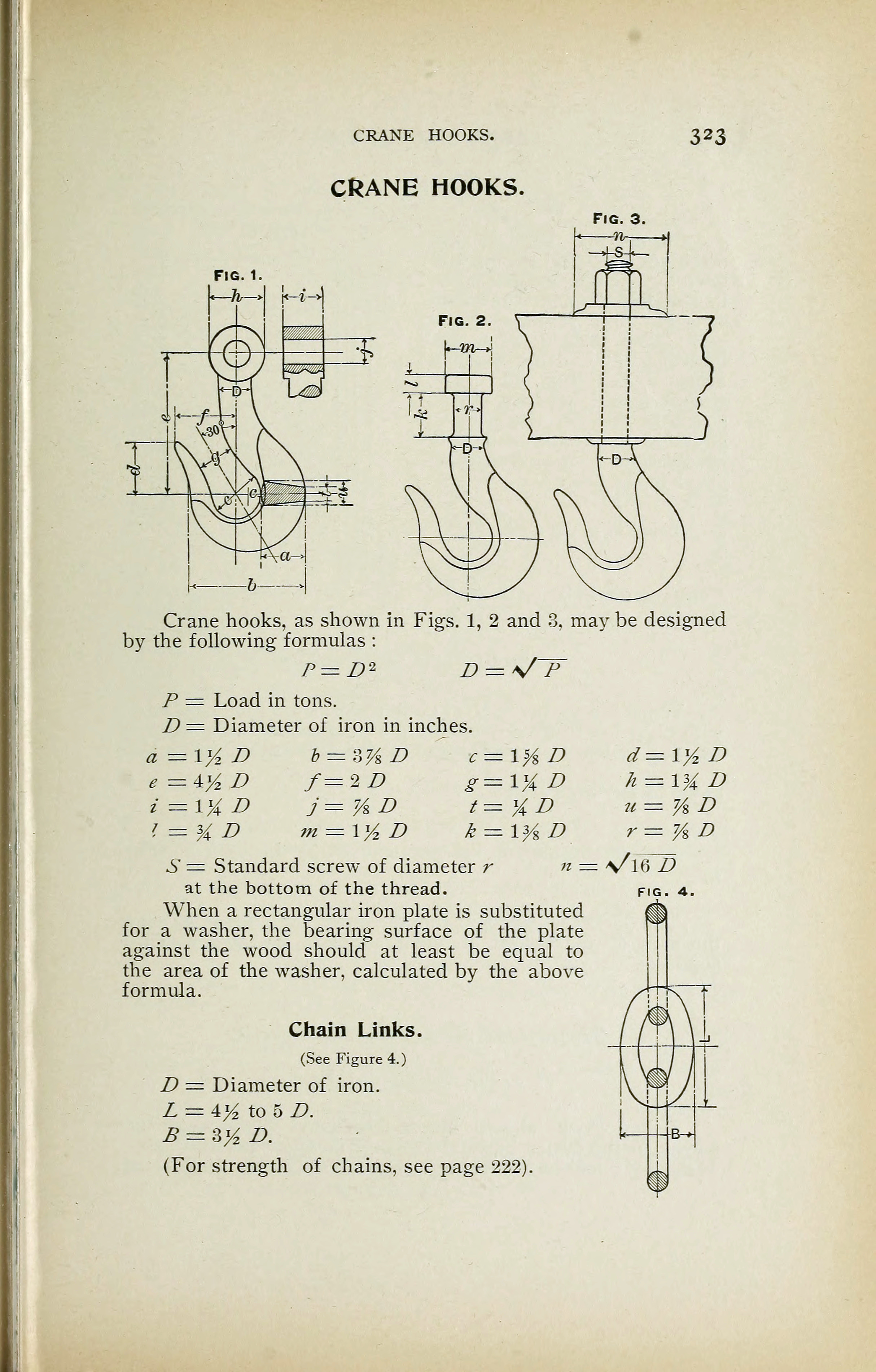
Crane hooks, as shown in Figs. 1, 2 and 3. may be designed
by the following formulas :
P=B2 D^s/’F
P = Load in tons.
D = Diameter of iron in inches.
e=±y
2 D f=2B g=l%D
i —\% D j=7/zD t=%D
i = y
A D m = iy
2 D k = iy
s L>
S = Standard screw of diameter r n
at the bottom of the thread.
When a rectangular iron plate is substituted
for a washer, the bearing surface of the plate
against the wood should at least be equal to
the area of the washer, calculated by the above
formula.
Chain Links.
(See Figure 4.)
D = Diameter of iron.
L = 4y
2 to 5 D.
B = sy
2 n.
(For strength of chains, see page 222).
<< prev. page << föreg. sida << >> nästa sida >> next page >>