
Full resolution (JPEG) - On this page / på denna sida - Back-Scattering Cross Section of Reactively Loaded Cylindrical Antennas, by Bengt-Olof Ås and Hans J. Schmitt
<< prev. page << föreg. sida << >> nästa sida >> next page >>
Below is the raw OCR text
from the above scanned image.
Do you see an error? Proofread the page now!
Här nedan syns maskintolkade texten från faksimilbilden ovan.
Ser du något fel? Korrekturläs sidan nu!
This page has never been proofread. / Denna sida har aldrig korrekturlästs.
Fig. 1. Centre-loaded antenna.
trie vector of the incident wave is parallel to the
axis of the cylinder, the scattered field has circular
uniformity around the axis.
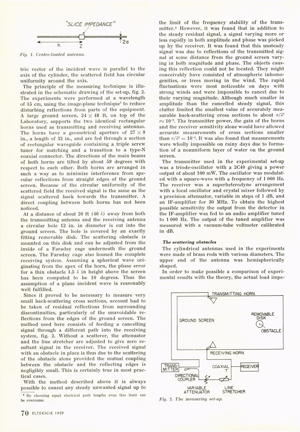
The principle of the measuring technique is
illustrated in the schematic drawing of the set-up, fig. 2.
The experiments were performed at a wavelength
of 15 cm, using the image-plane technique5 to reduce
disturbing reflections from parts of the equipment.
A large ground screen, 24 x 48 ft, on top of the
Laboratory, supports the two identical rectangular
horns used as transmitting and receiving antennas.
The horns have a geometrical aperture of 27 X 8
in., a length of 32 in., and are fed through a section
of rectangular waveguide containing a triple screw
tuner for matching and a transition to a type-N
coaxial connector. The directions of the main beams
of both horns are tilted by about 59 degrees with
respect to each other. Both horns are arranged in
such a way as to minimize interference from
specular reflections from straight edges of the ground
screen. Because of the circular uniformity of the
scattered field the received signal is the same as the
signal scattered back towards the transmitter. A
direct coupling between both horns has not been
noticed.
At a distance of about 20 ft (40 A) away from both
the transmitting antenna and the receiving antenna
a circular hole 12 in. in diameter is cut into the
ground screen. The hole is covered by an exactly
fitting removable disk. The scattering obstacle is
mounted on this disk and can be adjusted from the
inside of a Faraday cage underneath the ground
screen. The Faraday cage also housed the complete
receiving system. Assuming a spherical wave
originating from the apex of the horn, the phase error
for a thin obstacle 1.5 A in height above the screen
has been computed to be 10 degrees. Thus the
assumption of a plane incident wave is reasonably
well fulfilled.
Since it proved to be necessary to measure very
small back-scattering cross sections, account had to
be taken of residual reflections from surrounding
discontinuities, particularly of the unavoidable
reflections from the edges of the ground screen. The
method used here consists of feeding a cancelling
signal through a different path into the receiving
system, fig. 2. Without a scatterer, the attenuator
and the line stretcher are adjusted to give zero
resultant signal in the receiver. The received signal
with an obstacle in place is thus due to the scattering
of the obstacle alone provided the mutual coupling
between the obstacle and the reflecting edges is
negligibly small. This is certainly true in most
practical cases.
With the method described above it is always
possible to cancel any steady unwanted signal up to
* By choosing equal electrical path lengths even this limit can
be overcome.
the limit of the frequency stability of the
transmitter.* However, it was found that in addition to
the steady residual signal, a signal varying more or
less rapidly in both amplitude and phase was picked
up by the receiver. It was found that this unsteady
signal was due to reflections of the transmitted
signal at some distance from the ground screen
varying in both magnitude and phase. The objects
causing this reflection could not be located. They might
conceivably have consisted of atmospheric
inhomo-genities, or trees moving in the wind. The rapid
fluctuations were most noticeable on days with
strong winds and were impossible to cancel due to
their varying magnitude. Although much smaller in
amplitude than the cancelled steady signal, this
clutter limited the smallest value of accurately
measurable back-scattering cross sections to about o/X"
■pst 10~3. The transmitter power, the gain of the horns
and the receiver sensitivity alone would have allowed
accurate measurements of cross sections smaller
than o/P = 10~4. It was also found that measurements
were wholly impossible on rainy days due to
formation of a nonuniform layer of water on the ground
screen.
The transmitter used in the experimental set-up
was a triode-oscillator with a 2C40 giving a power
output of about 100 mW. The oscillator was
modulated with a square-wave with a frequency of 1 000 Hz.
The receiver was a superheterodyne arrangement
with a local oscillator and crystal mixer followed by
a precision attenuator, variable in steps of 1 dB, and
an IF-amplifier for 30 MHz. To obtain the highest
possible sensitivity the output from the detector in
the IF-amplifier was fed to an audio amplifier tuned
to 1 000 Hz. The output of the tuned amplifier was
measured with a vacuum-tube voltmeter calibrated
in dB.
The scattering obstacles
The cylindrical antennas used in the experiments
were made of brass rods with various diameters. The
upper end of the antenna was hemispherically
shaped.
In order to make possible a comparison of
experimental results with the theory, the actual load impe-
Fig. 2. The measuring set-up.
.70 ELTEKNIK 1959
<< prev. page << föreg. sida << >> nästa sida >> next page >>