
Full resolution (JPEG) - On this page / på denna sida - N:o 12. Dec. - Sidor ...
<< prev. page << föreg. sida << >> nästa sida >> next page >>
Below is the raw OCR text
from the above scanned image.
Do you see an error? Proofread the page now!
Här nedan syns maskintolkade texten från faksimilbilden ovan.
Ser du något fel? Korrekturläs sidan nu!
This page has never been proofread. / Denna sida har aldrig korrekturlästs.
SKF BEARINGS IN THE AUTOMOBILE
The application of S K F bearings for
general engineering purposes is accompanied
by a technical service which carries
considerable weight with an engineer not fully
conversant with the principles involved. The
situation with regard to automobile work however, is
rather different. Many designers can look back
upon twenty years’ experience of anti-friction
bearings and their views on the selecting, fitting,
and maintenance of them have become settled
convictions.
This knowledge of the subject, strangely enough,
is not accompanied by a really intimate
acquaintance with the stresses present in ball or roller
bearings, and in addition it is very rare to find an
Automobile Drawing Office in which there is any
record of load analysis having been carried out.
The layout of a new chassis simply involves a
painstaking overhaul of all available information
regarding similar designs, and practice, in short,
is the guide to bearing selection as it is to the
settlement of many other points.
It has long been appreciated by S K F that the
selection of ball bearings on a basis of the
maximum load at the ruling speed without reference
to the fatigue factor is inadmissible. The bearings
would be altogether too costly. The qualification
by fatigue has, however, been on a purely
practical basis, and SKF research in this direction has
lifted the entire subject to a higher level of
treatment altogether. British practice was originally
based on a combination of ball and roller
construction of generous dimensions, all side shocks and
continuous thrusts being handled by thrust
bearings. The increasing confidence of the American
designer in the double purpose unit has so far not
found its reflection in the factories in England,
but there is every evidence that the work of S K F,
the last 12 months in this direction, will bear
excellent fruit.
SKF can point to an imposing array of
high-class British Cars in which our products have
found a field, but the general stagnation in
business has made it more imperative than ever to
observe costs. Our campaign has consequently
been directed with the object of giving the
maximum technical service with its accompanying
financial expression. The chassis layout is
obtained and promptly analysed by the Technical
Department, the result being a complete statement
of the loads at every point of application, and the
factors of safety with reference to our catalogue
ratings. The possibility of eliminating thrust
bearings in the differential or elsewhere is carefully
reviewed and the final estimate for the bearings
frequently shows an attractive reduction in capital
outlay.
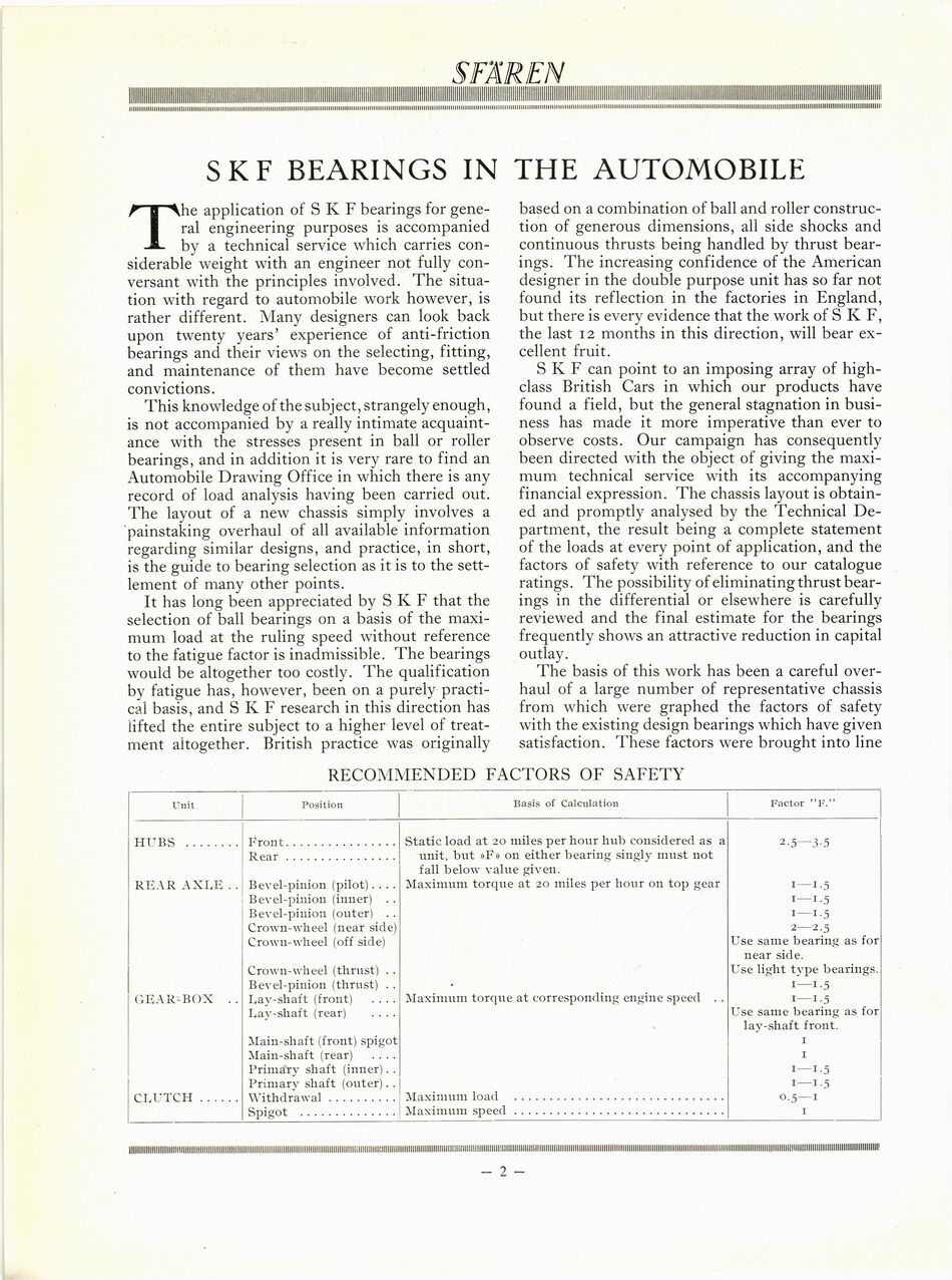
The basis of this work has been a careful
overhaul of a large number of representative chassis
from which were graphed the factors of safety
with the existing design bearings which have given
satisfaction. These factors were brought into line
RECOMMENDED FACTORS OF SAFETY
Unit I Position Basis of Calculation Factor "F."
HUBS ........ Front................................Static load at 20 miles per hour hub considered as a 2.5—3.5
Rear................................unit, but »F» on either bearing singly must not
fall below value given.
REAR AXLE . . Bevel-pinion (pilot).... Maximum torque at 20 miles per hour on top gear 1—1.5
Bevel-pinion (inner) . . 1—1.5
Bevel-pinion (outer) .. 1—1.5
Crown-wheel (near side) 2—2.5
Crown-wheel (off side) Use same bearing as for
near side.
Crown-wheel (thrust) . . Use light type bearings.
Bevel-pinion (thrust) .. • 1—1.5
GEAR-BOX .. Lay-shaft (front) .... Maximum torque at corresponding engine speed .. 1—1.5
Lay-shaft (rear) .... Use same bearing as for
lay-shaft front.
Main-shaft (front) spigot 1
Main-shaft (rear) .... 1
Primary shaft (inner).. 1—1.5
Primary shaft (outer).. 1—1.5
CLUTCH...... Withdrawal....................Maximum load ............................................................0.5—1
Spigot ............................Maximum speed ............................................................1
<< prev. page << föreg. sida << >> nästa sida >> next page >>