Full resolution (JPEG) - On this page / på denna sida - Fly Wheels - Centrifugal force in fly-wheel and pulleys - Rules for calculating safe speed of fly-wheels - Rule for calculating safe diameter of fly-wheels - Shafting

<< prev. page << föreg. sida << >> nästa sida >> next page >>
Below is the raw OCR text
from the above scanned image.
Do you see an error? Proofread the page now!
Här nedan syns maskintolkade texten från faksimilbilden ovan.
Ser du något fel? Korrekturläs sidan nu!
This page has never been proofread. / Denna sida har aldrig korrekturlästs.
3^0 f FLY-WHEELS.
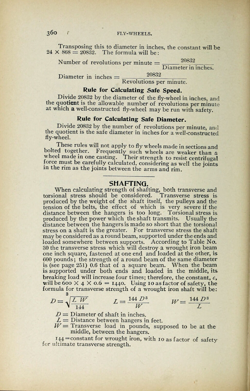
Transposing this to diameter in inches, the constant will be
24 X 868 = 20832. The formula will be
:
Number of revolutions per minute = 20832
Diameter in inches.
Diameter in inches -
Revolutions per minute.
Rule for Calculating Safe Speed.
Divide 20832 by the diameter of the fly-wheel in inches, and
the quotient is the allowable number of revolutions per minute
at which a well-constructed fly-wheel may be run with safety.
Rule for Calculating Safe Diameter.
Divide 20832 by the number of revolutions per minute, and
the quotient is the safe diameter in inches for a well-constructed
fly-wheel.
These rules will not apply to fly wheels made in sections and
bolted together. Frequently such wheels are weaker than a
wheel made in one casting. Their strength to resist centrifugal
iorce must be carefully calculated, considering as well the joints
in the rim as the joints between the arms and rim.
SHAFTING.
When calculating strength of shafting, both transverse and
torsional stress should be considered. Transverse stress is
produced by the weight of the shaft itself, the pulleys and the
tension of the belts, the effect of which is very severe if the
distance between the hangers is too long. Torsional stress is
produced by the power which the shaft transmits. Usually the
distance between the hangers is made so short that the torsional
stress on a shaft is the greater. For transverse stress the shaft
may be considered as a round beam, supported under the ends and
loaded somewhere between supports. According to Table No.
30 the transverse stress which will destroy a wrought iron beam
one inch square, fastened at one end and loaded at the other, is
600 pounds ; the strength of a round beam of the same diameter
is (see page 251) 0.6 that of a square beam. When the beam
is supported under both ends and loaded in the middle, its
breaking load will increase four times; therefore, the constant, c,
will be 600 X 4 X 0.6 = 1440. Using 10 as factor of safety, the
formula for transverse strength of a wrought iron shaft will be:
D = J~Z7W /- 144 D* 144/73
>HU4~ W L
D = Diameter of shaft in inches.
L = Distance between hangers in feet.
W= Transverse load in pounds, supposed to be at the
middle, between the hangers.
i44=constant for v/rought iron, with 10 as factor of safety
for ultimate transverse strength.
<< prev. page << föreg. sida << >> nästa sida >> next page >>